Article

Q&A with Bradley Falcus

- by
Tags: Featured

Full Name: Bradley Falcus

Job Title: Senior Geo-Environmental Administrator

Company: Central Alliance Pre-Construction Services Ltd

I’m an early career professional who believes that the power of people can never be underestimated, nor should it be underappreciated. Over the past four years since my masters degree, I have become experienced in the geotechnical sector working in archaeology, geophysical exploration and ground engineering. I have quickly adapted to a management role within this timeframe, developing a team of trained geo-environmental and business administrators before the age of 30. I am passionate and driven to make a difference in the geotechnical sector, be that business-by-business, or wider reaching to the AGS’ members.

Are there any projects which you’re particularly proud to have been a part of?

I suppose my answer to this is split into two, one for my role within Central Alliance and one for my role within RSK. Working as one of the Data Managers on the Wales and Western Framework (Network Rail) has been a fantastic opportunity for me to learn and develop. The role is multifaceted and requires a great attention to detail and seems to continue to grow arms and legs with every week that passes. I enjoy working with my colleagues at Central Alliance on framework projects like this, it gives me the opportunity to work closer with them as part of the project management team and share in the delivery of great results to our client.

Within the wider RSK Group, I am a co-chair of the RSK Pride Network, an employee ran network which supports and welcomes LGBTQ+ people in the workplace. In July 2023, RSK were one of the sponsors of Bristol Pride. We brought together staff members from across the UK and had a wonderful celebration of our RSK Family. I can honestly say it has been an amazing event to organise and run – hopefully we’ll have more like it in the future and maybe we can extend the invite to other AGS members.

What are the most challenging aspects of your role?

Time! I think with a role like mine, it’s quite easy to forget when to switch off. Some days it will be nine hours of meetings, some days it will be nine hours of tender compilations, some days it will be nine hours providing training. Every day is different from the one before it; and even though that makes it interesting, it can be overwhelming if you don’t have the right procedures in place. Best advice from me is to make sure you take time for yourself, in and out of your work hours – don’t be a martyr to Ground Investigation by slaving away for hours and hours.

You have recently joined the AGS Business Practice WG to help develop Equity, Equality, Diversity and Inclusion within the AGS. What are your aspirations for the AGS?

Two of the UN Sustainable Development Goals are Gender Equality and Reducing Inequalities; these are targets that we as an industry have to take seriously going forward. I believe that trade associations like the AGS have a fundamental role to play in changing the attitudes of businesses across the UK and internationally on how we can be more equal and inclusive. I really do have aspirations that the AGS will be able to champion employment equality and equity, increase graduate opportunities and to represent the underrepresented. I hope that we can, as the BPWG, spark conversations around the topic of reducing inequalities across our industry and continue to welcome generations of new bright minds to the fold.

What do you enjoy most about being an AGS Member?

I love being able to connect with so many intelligent and interesting people that are part of the AGS. It’s inspiring as a young professional (I think I qualify for that title) to attend conferences and webinars to learn from the vast amount of experience there is in the group. Personally, I cannot wait for the next in-person meeting and hope to see many friendly faces there.

What do you find beneficial about being an AGS Member?

Being able to keep on the pulse of all the updates from the geotechnical and geoenvironmental sector – rules, regulations, guidance and procedure change so quickly, it’s always good to be part of the movement than behind it. Also being able to interact with the different working groups is invaluable, by attending conferences and meetings you have the opportunity to shape the future of the geotechnical industry.

Why do you feel the AGS is important to the industry?

The AGS is one of the best platforms for collaboration in our industry –  Helen Keller, an activist for disabled rights, said that ‘Alone we can do so little, together we can do so much’ and I think about that quote quite a lot and what it means for us. It’s important to know that we aren’t as secular or ‘alone’ as we sometimes believe to be. The AGS is a shining example of fantastic minds, creative people and keen advocates coming together for the future of our sector.

What changes would you like to see implemented in the geotechnical industry?

In my dreams? I would love to have collaborative networks created between AGS member businesses which minority communities (for example: POC, LGBTQ+, people who are neurodivergent, people who are disabled, etc) would be invited to join. These networks could have regular meetings, chaired by the AGS, where they would be able to give direct feedback and guidance on what the industry can improve upon. I’d hope we could create a welcoming space for all people to join us from all backgrounds and ensure that their voices are heard. In the meantime, I would love to see guidance from the BPWG on tackling unconscious bias and good hiring practices in our industry as a fundamental step in the right direction.

Article

Inside Geosense

- by
Tags: Featured

Name: Tim Clegg

Job title: Managing Director

Company name: Geosense Ltd

What does the company do and what areas does it specialise in?

Geosense is a leading UK manufacturer and global supplier of Geotechnical Instruments and data acquisition systems. We specialise in the design and manufacture of MEMS and Vibrating Wire monitoring sensors which are used in many sectors including site investigation, dams, bridge, deep excavations, infrastructure, mining and more.

Where is Geosense located?

We have a purpose-built manufacturing facility in Suffolk.

How many people does the company employ?

Currently 59. Interestingly, three years ago it was around half that, but we have needed to grow to meet the rising demand for our products. We recruit mainly from the local area, with many of our staff joining us as school levers and working their way through the business to hold managerial roles. Since Covid, we have also been able to expand some roles to fully remote working with two members of the sales team based in Manchester and a member of technical support near Oxford. We have also recently employed our first overseas employee in the US.

How long have you worked at Geosense?

I worked part time during school holidays from the age of 16. My full-time role at Geosense started in 2013 so I would say I have been at Geosense 10 years. Time does fly!

What is your career background, and what enticed you to work for Geosense?

My career background is short! I started as a pot washer at a local pub and worked at a local supermarket before heading off to the University of East Anglia in Norwich. I studied Economics for 3 years before joining Geosense assisting in the production department.

Geosense is a family business but working at Geosense was not always a route I wanted to go down, nor one which was expected. However, I can say I love my job and consider myself lucky to have the opportunity to work in this industry.

Knowing what I know now, the best part of working at Geosense is the exciting projects we work on, and the people we work with. This industry is full of passionate people who genuinely care about the work we do and the value we provide on every project.

What is your current role within Geosense and what does a typical day entail?

I am currently Managing Director. A typical day? I am incredibly lucky that I get to work across multiple departments all performing important functions in the business. Officially my role is to ensure everyone is happy and to make decisions on current and future strategy. Unofficially I do anything that is required on any given day.  In short, I get to work with a great team to make some very exciting stuff happen.

This week I have been working with our software developer on an exciting new development digitising our calibration data. I was also looking at new types of sustainable packaging and had a 6am call with Singapore and a trip to the Houses of Parliament. As I said, quite varied!

Having been Commercial Manager, Sales and Customer relationships is what I know and I help a great team who look after our customers across the globe. Customer care and support is key to every member of the Geosense team.

What are the company’s core values?

We recently did a workshop with the whole company to put forward and agree on our companies values as we enter into an exciting period of growth in the company. The company has grown significantly, and we wanted to develop new values that could help us navigate the future whilst recognising what made us successful. We chose the following:

Open & Honest Communication

Care & Respect

Collective Responsibility

Client Focused

Agile

These values embody what Geosense is and how we want to work, they were decided and agreed by every single member of staff.

Are there any projects or achievements which Geosense are particularly proud to have been a part of?

In 2022 Geosense was one of 141 companies in the UK to win a Queens Award for Enterprise for International Trade. Seen as the most prestigious award a UK company can receive, we are particularly proud that the certificate was one of the last to be signed by the late Queen Elizabeth II. The main thing is that it recognised the hard work and skill of every single member of the company, past and present, during the last three years.

As for projects, we are proud to have been involved in many well-known UK projects such as Tower Bridge, Tideway, HS2, Battersea Power Station, HARP and Woodsmith Mine, to name but a few.

I am hugely proud when I walk around London and know that our sensors have helped monitor some of the capital’s most iconic structure. Often very frustrating for friends and family who join me scouring buildings for the total station or dataloggers!

How important is sustainability within the company?

As a responsible modern business, we have sustainability in mind on what we do right now and our plans moving forward. Our production facility is heated/cooled using ground source geothermal and our roof is full of solar panels.

We have an internal environmental committee, with members from all areas of the business discussing and creating our vision to have as small as possible negative impact on the planet. We are also currently implementing a roadmap to zero plastic packaging for all products.

Recently we digitised all our calibration data which means that we will be phasing out paper calibration records in favour of QR code-driven digital records. If clients do want paper copies, we will be donating £1 for every paper copy to Forestry England.

We are a proud UK manufacturer and, where possible, keep the majority of our supply chain within the local area and the UK. We firmly believe in managing a sustainable supply chain.

How does Geosense support graduates and early career professionals who are entering the industry?

We are big advocates of training and personal development for our staff. A number of the team are completing formal qualifications as part of their roles at Geosense.

Geosense has always been proactive in providing training and support for engineers. Recently we launched our Geosense Academy which provides tailored training on our products/applications to a wide range of professionals, including graduates and early career professionals. To date over 80 engineers have been through the academy.

We are always open to summer placements for graduates if they want to learn more about the industry or manufacturing.

How has COVID-19 impacted Geosense today? Are there any policies which were made during the pandemic that have been kept to improve employee wellbeing and productivity?

I think the main impact that should be addressed is the affect that COVID had on everyone’s wellbeing. I am very glad that this is now something that is being discussed more and businesses are taking a more active role in managing wellbeing. At Geosense, we have increased the number of mental health first aiders to 5, and also offer an EAP system to offer support to staff. We are also providing food in the canteen to help ease some of the burden of the cost of living for our staff.

Flexible working was already being implemented but COVID certainly sped things up for us! Since COVID we have continued with flexible working and have also introduced flexible working patterns for production which has been really well received.

One small thing we introduced in the sales team was a Monday morning meeting where the first section of the meeting was to go through what everyone did at the weekend, with a Friday meeting to share what the plans were for the weekend. This made the meetings not just about business and made a huge difference during COVID. At least the things we do at the weekend now are a lot more exciting than they were during COVID!!

Why do you feel the AGS is important to the industry?

I must admit I used to think the AGS was mainly centred around data format.

However, having attended many conferences and being involved in the AGS I&M working group, I have seen a large group of passionate professionals who want to help standardise the industry and make the use of Geotechnical methods as easy and useful as possible. Also, while a lot of our work is construction aligned, we often get ‘lost’ within the construction industry bodies. The AGS fulfils an important role for the sharing of ideas and discussing how best to pass this information to different parts of the wider industry,

I now see the AGS as a group who want things done properly in our industry!

What are Geosense’s future ambitions?

To grow while still enjoying the journey!

Our industry is experiencing an exciting period with great innovation and increased adoption. We are at a point we can shape and point the industry in a good direction.

With greater connectivity options, digital innovations, and the ability to do more with data the future is very bright indeed.

Article

London Build 2023

- by
Tags: Featured

The UK’s leading construction show returns to Olympia London’s Grand Hall on November 15th & 16th.

London Build offers thousands of unique experiences over the two days with 500+ incredible speakers across 8 stages, 350+ exhibitors, Meet the Buyers, live product demos, networking parties, entertainment, live music, the UK’s biggest Festival of Construction and endless networking opportunities with leading architects, developers, housebuilders, contractors, government and more.

Featuring:

  • 35,000+ registered visitorsfrom contractors, architects, civil engineers, developers, local councils, house builders/associations and construction professionals
  • 500+ inspiring speakersacross 8 conference stages including Future of Construction, BIM & Digital, Fire Safety, Sustainability, Diversity & Inclusion and more
  • 200+ hours of CPDtraining and education
  • The UK’s biggest Festival of Constructionwith DJs, musicians, live performances, celebrity guests, entertainment and competitions
  • Meet the Buyers with Procurement Teams exhibiting from Balfour Beatty, Skanska, Mace Dragados, BAM UK, Costain, SMP Alliance and more
  • Architect’s Hub with project displays and 3D models of upcoming projects from leading architects across the UK
  • The latest insightsand updates on major upcoming construction projects and opportunities across the UK
  • Exclusive networking eventsco-hosted with Urbano Build, London Constructing Excellence Club, Forum for the Built Environment, The CIOB, Building People, Let’s Build, Building Equality and many more
  • The UK’s largest networking events for Women in Constructionand Diversity in Construction
  • An inclusiveAmbassador Programme supporting Women in Construction, Diversity in Construction and Mental Health in Construction
  • 350+ exhibitors showcasing the latest services, products and innovations transforming the industry

Register for tickets at www.londonbuildexpo.com/

News

AGS Magazine: July 2023

- by
Tags: Featured

The Association of Geotechnical and Geoenvironmental Specialists is pleased to announce the July 2023 issue of their publication; AGS Magazine. To view the magazine click here.

This free, publication focuses on geotechnics, engineering geology and geoenvironmental engineering as well as the work and achievements of the AGS.

There are a number of excellent articles in this issue including;

Geotechnica 2023: Conference Lineup Confirmed – Page 8

AGS Ground Risk Conference: Are you Managing Risks or Taking Risks? – Page 10

Assessment and Mitigation of Turbidity Risks from Piling – Page 18

A comprehensive comparison of field-based analytical technologies for both qualitative and quantitative determination of petroleum hydrocarbons in soils – Page 26

Findings of SiLC DoWCoP industry survey: Regulatory challenges for regeneration of historical landfills and reuse of stockpiles and mineral waste – Page 32

Guidance on the opening of core and dynamic sampler liner – Page 36

Plus much, much more!

Advertising opportunities are available within future issues of the publication. To view rates and opportunities please view our media pack by clicking HERE.

If you have a news story, article, case study or event which you’d like to tell our editorial team about please email ags@ags.org.uk. Articles should act as opinion pieces and not directly advertise a company. Please note that the publication of editorial and advertising content is subject to the discretion of the editorial board.

Article Safety

Guidance on the Opening of Core and Dynamic Sampler Liner

- by
Tags: Featured

Introduction

For engineering geologists in the UK ground investigation industry, the opening of core and dynamic sampler liners to enable the logging of recovered material is a standard and often daily procedure. This operation is frequently carried out onsite, under field conditions, using a variety of tools including knives to complete the task effectively.

Statistics on accidents involving knives within the geotechnical and environmental sector aren’t readily available, however relevant information is accessible from the UK plastics industry. Reviewing four separate plastics manufactures with online published information our research indicated;

  1. A plastic film manufacturer identified that hand knife injuries contributed to over 50% of their total accidents.
  2. A polyethene manufacturer indicated that over 50% of their accidents were hand injuries.
  3. A plastic components manufacturer appointed a new safety manager who noticed that hand knife injuries accounted for a significant percentage of the company’s total injuries.
  4. A pipe extrusion company noted that their largest category of injuries were cuts, and of these 75% were caused by knives.

Within the ground investigation industry there are many anecdotal incidents where operatives and logging engineers have caused serious harm to themselves whilst using knives, and it is more than likely that injuries involving the use of knives is more common than those instances that are reported.

The aim of this article is to explore the methods available to the engineer in the field and provide guidance on the safe cutting of core and dynamic sampler liners.

The use of knifes and other cutting devices is covered by The Provision and Use of Work Equipment Regulations 1998 (PUWER 1998), which requires work equipment to be suitable and safe for the task it is being used for.

The only focused advice from the Health and Safety Executive (HSE) is How to reduce hand knife injuries. HSE PPIS12(rev1) May 2000. However, this is not specific to the construction industry but provides practical advice to anybody involved in managing the risks of using hand knives as part of their work.

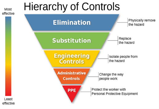
As with all risks associated with work activities, a risk assessment is required to identify the risk and put into place suitable and sufficient control measures to reduce the risk. When considering risk controls for core and dynamic sampler liner cutting it is important to select the most effective control measure, this is achieved by considering the hierarchy of controls.

As highlighted by the graphic, the most effective risk controls are elimination, substitution and engineering controls, weaknesses within administrative controls and personal protective equipment are created through the reliance on humans to follow rules. Where this reliance can be removed, more effective controls have a positive impact on reducing harm.

Considering, the hierarchy of controls application to core and dynamic sampler liner cutting mitigation, the following could be considered:

Elimination: alternatives to core liner could be identified that eliminate the use of knifes or the need to cut liners. Consideration should be given to different techniques which may eliminate the need to cut core liners or in fact not use core liners at all.

Substitution: can be applied to the core liner itself, identify alternative types of liners which are easier to cut and reduce the effort used to cut the liner improving knife control and reducing the risk of cutting. The volume of core liners produced can also potentially be reduced, through the reduction of intrusive locations, the use of other investigative methods (e.g. CPTs) or substituting some of the field work for computer modelling utilising AI based technologies.

Engineering Controls: provide significant options to reduce cutting associated with core liners, from specifying safety knifes with self-retracting or hidden blades or by the introduction of purpose-built core liner cutters, jigs for powered tools or other mechanical options.

Administrative Controls: in relation to fixed blades bans within site rules and procedures or alternative equipment detailed within method statements. These controls have weaknesses surrounding implementation, as they need greater levels of supervision and trust of the operatives and fixed blade knifes have a habit of finding their way onto site.

Personal Protective Equipment: is universally used on every project and sometimes overused, throwing PPE at a problem without taking the time to understand the holistically to begin with. Cut resistant gloves, gauntlets and other protective items have been significantly improved in recent years, providing good dexterity as well as high cut resistance.

Through the research required to write this article, consulting with people across the industry and those outside of it, methods of core and dynamic sampler liner cutting which significantly lower the risk of cuts to hands have been identified. These are not risk free, but in practice significantly reduce the risk of significant hand injuries when compared to the use of fixed blade knifes which should not be used for core and dynamic sampler liner cutting.

Core Line Cutting Rig

In a purpose-built logging shed core liners can be cut using a bench and cutting rig arrangement where liners are put within a rigid frame and the liners mechanically cut either by a hooked blade arrangement in a safety jig or vibratory cutter (noting that the introduction of vibrating tooling introduces vibration, noise and dust risks which need to be controlled). In either case the cutting is carried out without the need for the technicians/geologist fingers to be anywhere near the cutting edge, reducing the risk of injury. However, with what is available on the market today, this type of set up is almost certainly prohibitive in terms of suitability of the site environment when working in the field.

Oscillating Blades and Smalls Grinders

The use of oscillating blades (preferred due to safer handling) and small grinders is a technique that can be beneficially used where the cores and liner can be placed in a rigid structure (such as a core box), and at a suitable height for the operator to ensure ergonomic working practices, reducing the risk of musculoskeletal injuries. This can be achieved in the field by using trestles or the open tailgate of a truck. Rechargeable battery units should be preferred to eliminate introducing the additional risk of trailing cables and electric shock.

Using Oscillating Blades and Smalls Grinders will introduce additional hazards which must be controlled through the introduction of suitable and sufficient controls, these include: manual handling, flying debris and dust, noise, vibration and the potential damage to the core/sample itself through overcutting.

Safety Cutters

There are a number of different safety cutters available to the industry which are capable of cutting core and dynamic sampler liner. These types of cutters prevent the small surface area of the blade coming into contact with the fingers.

Unfortunately this type of cutter is often the source of great frustration when they fail to work either due to user error or their lack of suitability for the task in hand, particularly when they were too wide to get between the core and the core liner. It is well documented that when such frustrations occur it is human nature to bypass the agreed procedures and revert to fixed blade knifes and inaccurate statements made that ‘all safety cutters will not work’.

Due to these very real risks, the selection and testing of safety cutters is imperative to ensure that the tools are fit for purpose, task and the environment which they are used in.

Safety Knives

There are a number of different safety knifes available in the marketplace. These type of knifes have an automatically retracting blade when pressure is released from the blade. These will then require resetting before the blade is re-exposed.

As safety knifes work using the same manual techniques as a fixed blade knife, their use, provided the correct knife has been selected for the task, is more widely accepted by those within the industry and they do not require controls to be introduced.

When using retractable safety knifes, if they are poor maintained, they are susceptible to being damaged by rusting and the mechanism clogged by debris, eventually preventing it from working effectively. This, together with other maintenance and user information should be documented into administrative controls to support their effectiveness.

As with any task, training should be provided on how to open core liners and other samples safely, regardless to which of the above techniques are employed. This training should cover the core cutting methodology, how to replace blades on retractable knives, regular cleaning and maintenance of cutting tools.

When considering the task itself it is important to place the liner in a fixed sturdy location such as a core box or other configuration that holds the liner firmly in place, place the knife perpendicular to the core, facing away from the body at a 45o angle and ideally use two hands, pull the knife allowing slow controlled cuts, avoiding the jerking action that often leads the knife slipping.

Consideration in using this method should be given to the strength and dexterity of the person cutting the liner. Additionally, certain types of core liner can be prone to shattering and splintering when cut. The operator shall remain vigilant at all times when cutting liners in case they are fragile and the cutting methodology reassessed.

Other basic controls when handling knifes should be applied, even when using safety knifes, these consist of but are not limited to;

  • Not handing a knife to a work colleague. Instead, lay it on a flat surface for them to pick up.
  • Keep the thumb of the hand using the cutter away from the blade, and your other hand far enough away to avoid laceration.
  • Knife blades should be kept sharp and knives maintained and checked before use.
  • Any damaged or knives or blades should be disposed of in a safe manner.
  • Ensure there is good lighting available where the task is being undertaken.
  • When done with a knife, store it edge-down or covered.

As with all cutting activities, they should be supported using appropriate PPE including cut-resistant gloves, safety footwear, eye protection and clothing to cover exposed arms and legs. Although cut resistant gloves and forearm gaiters cannot eliminate the risk of getting injured entirely, they can reduce the severity of the injury.

The right kind of cut-resistant glove to purchase is the one that best protects the user from the hazards they face. Heavy duty gloves or gloves that are too large for the individual will affect the dexterity of the user and they may be tempted to remove the gloves, which exposing them to risk. Always ensure that when selecting gloves, cut resistant and dexterity are considered.

Summary

The cutting of core and dynamic sampling liner within the geotechnical industry will remain an important part of the normal operations of field based engineers. Knives are the most commonly used hand tool for this type of activity, however they require proper selection, application, and training in use and storage. The improper use of cutting tools and knives can lead to significant hand injuries, however using a simple risk assessed approach, the severity and likelihood of injuries sustained can be greatly reduced if not eliminated.

Article provided by Liz Withington (Principal Engineering Geologist, CC Ground Investigations) and Adam Latimer (Director, Ian Farmer Associates)

Article Contaminated Land

A comprehensive comparison of field-based analytical technologies for both qualitative and quantitative determination of petroleum hydrocarbons in soils

- by
Tags: Featured

Petroleum hydrocarbons are common soil contaminants that pose a risk to human and environmental health. Different analytical methods are used to determine their presence in soil, including non-specific screening techniques and lab-based fingerprint techniques. While the latter provides high accuracy, they can be time-consuming and expensive. Over the past decade, the emergence of various field analytical techniques, such as test kits and portable handheld devices, have enabled real-time petroleum hydrocarbons detection and measurement on-site, which has the potential to drastically reduce cost and time of analysis compared with traditional technologies and without sacrificing ‘Quality Management’ objectives. However, their performance for different soil types, contamination levels, and fuel types, as well as their ability to speciate and quantify different hydrocarbon groups for risk assessment, and their suitability for remediation monitoring and validation, have not been fully studied. It is also important to understand the type and quality of data that will be generated by field analytical technologies and interpretation of the data generated should be carefully evaluated before conclusions are drawn. Depending on which analytical technology is used, it is possible to achieve qualitative, semi-quantitative and quantitative results. In some cases, the accuracy of field analytical technology is approaching that achievable previously only from laboratory analysis. Yet, laboratory analysis may still be required to attain legally recognised measurements.

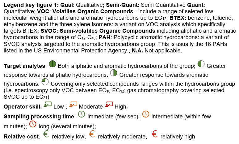
Figure 1: Summary of the criteria for selecting field analytical techniques for the analysis of petroleum hydrocarbon in soil

The main goal of this study was therefore to assess and raise awareness about the feasibility of using field-based techniques for determining TPH concentrations in soil, and whether they can replace lab processing. The study reviewed various techniques, ranging from high-end gas chromatographs and handheld infrared spectrometers to low-end oil pans and chemical kits. To ease comparison, the field analytical kits and devices were classified according to detection methods, target analytes detected and data quality levels (qualitative, semi-quantitative and quantitative) (Figure 1). The basic principle along the advantages and limitations of each field analytical technique, quality control requirements, operator skill level, and analysis cost are summarised and the synthesis can be accessed for free on the Concawe website at https://www.concawe.eu/wp-content/uploads/Rpt_21-3.pdf.

In general, the field analytical technologies for detecting petroleum hydrocarbons in soil are highly developed and well established. In terms of risk assessment, only GC-MS can accurately differentiate between aliphatic and aromatic petroleum fractions. However, this technique involves soil sample extraction and demands a high level of expertise, which may not be suitable for all projects. On the other hand, colorimetric, immunoassay, and turbidimetry test kits are cost-effective and rapid options for monitoring the reduction of petroleum hydrocarbons over time and guiding remediation strategies, but they lack specificity and do not provide information on individual analytes. Field spectrometry technologies offer real-time measurement of petroleum hydrocarbons in soil with minimal sample handling but require soil drying and cannot discriminate between aliphatic and aromatic fractions. Fluorescence technologies are used for in-situ site investigation with high spatial resolution but provide relative data and require skilled personnel. Both spectrometry and fluorescence systems can be useful in adaptive sampling designs to detect and predict contamination levels during the Phase 2 Investigation.

It is important to note that no single field analytical technology can quantify the entire range of petroleum hydrocarbons in soil, and therefore a combination of technologies may be necessary for greater accuracy in prediction.

Figure 2: Overview of the field and reference technologies evaluated for petroleum hydrocarbons determination in soil

A representative subset of seven field-based technologies was then selected and tested with impacted soil samples, which were compared to results from accredited laboratory analysis [Figure 2]. The subset included 3 portable solvent-based technologies (one portable GC-MS (FT1), one portable nondispersive infrared (NDIR) spectrophotometer (FT2), one portable ultraviolet fluorescence (UVF) spectrometer (FT3)), and 4 handheld solvent free technologies (one handheld visible and near-infrared reflectance (vis-NIR) spectrometer (FT4), two handheld Fourier-transform infra-red (FTIR) spectrometers (FT5 and 6), and one handheld photoionization detector (PID; FT7)). Three soils (sandy loam, silty clay loam, and clay loam) were spiked with gasoline or diesel fuel on weight/weight basis to achieve 100, 1000 and 10,000 mg/kg spike levels.

All samples were analysed for Total Petroleum Hydrocarbons (TPH), Volatile Organic Compounds (VOCs), Gasoline Range organic (GRO) and Diesel Range organic (DRO) and speciated hydrocarbon compounds when the chosen technology allowed to do so. Gasoline spiked soils were not analysed with FTIR and vis-NIR spectroscopy as the use of methanol as preservative interferes with the analysis. It has also been reported that non preserved samples contaminated with gasoline are subject to volatilisation losses that occur during the analytical process which result in poor performance for such technique. The intra and inter spikes consistency were evaluated by determining (1) precision from triplicates expressed as the percentage of relative standard deviation (%RSD) and (2) bias which is the difference expressed as a percentage between the mean of the replicate measurements and the spiked theoretical concentration level. Similarly, performance comparison of the field technologies against a benchtop GC-MS technology was carried out by determining the difference (%) between the mean measurements determined by the benchtop GC-MS and the field technologies evaluated. Additionally, performance characteristics of the GC-MS were determined by analysing the certified reference material RTC-SQC026 in triplicate.

All solvent-based field technologies performed well for TPH determination in different soil types, while solvent-free non-invasive technologies showed higher variability and lower accuracy. Infrared technologies are influenced by soil characteristics, particularly for low-level spikes (<1000 mg/kg) and certain soil types. The portable GC-MS performed well and closely to the benchtop GC-MS. While the headspace analysis of the portable GC-MS was easy to use and allowed to save time compared to the benchtop GC-MS, extra analysis time was required for the soil extraction and analysis due to manual injection. The non-destructive and solvent free Fourier-Transform IR (FTIR) and visible and near-infrared reflectance IR (vis-NIR) spectroscopic technologies performed well with diesel and demonstrated to be versatile, fast, and easy to use approach, but the accuracy was lower than for other technologies when total petroleum hydrocarbons (TPH) levels were <1000 mg kg-1. The procedures for soil calibration and validation may further limit the FTIR and vis-NIR applicability for diverse soil type and fuel type. In comparison, the non-dispersive IR (NDIR) and UVF spectroscopy technologies showed better performance, typically ±15% precision and ±30% bias for quantifying TPH in soil, which meet regulatory requirements. The UVF technology also provided additional quantitative information into hydrocarbons groups which can inform swiftly remediation monitoring and validation. Analysis of soil-gas samples by photoionization detector (PID) showed that PID underestimated concentrations compared to both portable and benchtop GC-MS which was expected as PID only provides an indirect and approximate indication of concentration of volatile compounds (VOC) in soil. Nevertheless, the PID remains a valuable instrument for site risk screening of soil-gas vapours considering its low cost and ease to use. Complete report is freely available on Concawe website at https://www.concawe.eu/wp-content/uploads/Rpt.22-12.pdf

The authors are grateful to all members of the Concawe Soil and Groundwater Taskforce (STF-33) which include a wide team of collaborators and advisors across Europe for their useful discussions and contribution during the study progress and revision of the reports.

Article produced by

Markus Hjort1, Eleni Vaiopoulou1, Richard Gill1,3, Pablo Campo4, Célia Lourenço4, Chris Walton4 , Tamazon Cowley4, and Frederic Coulon4

1Concawe (Scientific Division of European Fuels Manufacturers Association), Brussels, Belgium

2ExxonMobil (Esso Petroleum Company Limited), Avonmouth Fuels Terminal, St. Andrews Road, Avonmouth, Bristol, BS11 9BN, United Kingdom

3Shell Global Solutions International B.V., Carel van Bylandtlaan 30, 2596 HR, The Hague, Netherlands

4Cranfield University, School of Water, Energy and Environment, Cranfield, MK43 0AL, UK


Article Contaminated Land

Assessment and Mitigation of Turbidity Risks from Piling

- by
Tags: Featured

In recent years geo-environmental practitioners have experienced an increasing drive from regulators and water companies to assess risks to groundwater abstractions from turbidity that can be created by piling.  There is currently no authoritative UK guidance on how to assess this risk.

Piling operations present a number of potential risks to environmental receptors if not correctly managed.  These can include vibration and ground movement hazards, noise and creation of new pathways for contamination.  Geo-environmental specialists are familiar with assessing risks from piling related to contamination, with reference to the Environment Agency’s 2001 guidance (EA, 2001), however this does not cover turbidity.    The Environment Agency has recently commissioned CL:AIRE to update the guidance and it is understood that the revised version will refer to turbidity, but that the release date is unlikely to be before the end of 2023.  Planning consents for developments in sensitive areas such as the Source Protection Zone 1 (SPZ1) of a public water supply borehole often include conditions to assess and mitigate risks to the abstraction, and can specifically require turbidity to be assessed.

Why is Turbidity Assessment Required ?

Abstractors of groundwater are required by the Drinking Water Inspectorate to regularly test groundwater for turbidity.  The turbidity results are used as a marker for risks from pathogens such as Cryptosporidium and E. coli which the turbidity test does not differentiate from mineral particles.  Therefore, if increased turbidity is detected the operator has to shut down the abstraction until mitigation has been implemented (Burris et al, 2020).  This has significant implications for supply of water to local consumers and to the cost of water treatment.  Additionally, increased turbidity can compromise the disinfection process, and where the abstracted water is treated using membrane filters then the filters can become fouled by the turbidity, resulting in replacement costs running to potentially millions of pounds.   Operators of a site at which piling resulted in the shutdown of an abstraction could face significant financial and reputational liabilities.

The turbidity of water presented for disinfection must be less than 1.0 nephelometric turbidity unit (NTU), and in areas where background turbidity is elevated then water companies may apply their own more stringent criteria, which can be as low as 0.2 NTU.  These are lower than the UK Drinking Water Standard of 4 NTU when supplied at consumer’s taps (DWI, 2016).  For context, the image below shows water with 20 to 800 NTU.  The abstracted water target is clear to the naked eye and a turbidity sensor is required to detected turbidity < ~50 NTU.

The low target values that must be achieved by the abstractor therefore present significant challenge to the risk assessor.

How to Assess Risks ?

Review by others has not identified an authoritative methodology for quantifying risks (Burris et al, 2020), however a qualitative approach can be employed.  By development of a robust conceptual site model (CSM) similar to those used for contaminated land risk assessment, the potential risks can be qualitatively assessed.  The principles of source, pathway and receptor creating a potential pollutant linkage are similar to those set out in the Environment Agency’s Land Contamination Risk Management guidance (EA, 2021).  For the piling CSM the greatest emphasis is on the pathways and the source.  The development of a scale cross-section is strongly recommended to both inform the assessment and to communicate it to regulators.

Where qualitative assessment identifies potential risks, semi-quantitative assessment can be undertaken to better understand risks and inform mitigation measures.  In higher risk scenarios the CSM could be further developed with site-specific fracture details.

SOURCES

The primary source of turbidity during piling is mechanical action against the aquifer producing a microscopic rock ‘flour’ in suspension in groundwater, with different piling methods likely to result in different degrees of turbidity.  Loss of cement fines before cement has cured is also a concern.  The turbidity created will also be a function of the strata in which the piles are installed.  No studies were identified that quantify the turbidity created by piling.  However, qualitative assessment can quickly identify methods that are likely to create more turbidity.  Continuous Flight Auger (CFA) and other rotary methods are likely to generate turbidity, particularly when operating in rock or fine grained strata, due to the mechanical action of the rotating parts abrading the rock or soil.  For context, measurement of turbidity during drilling of 194mm diameter boreholes in Chalk using a tri-cone rock roller reported turbidity in thousands of NTU (maximum of 4,240 NTU) while rotary cored boreholes generated up to 452 NTU (Burris et al, 2020), although it is uncertain whether either would be representative of piling turbidity.  Conversely, driven piles are expected to produce less turbidity.

Particle size of the aquifer will be important in determining extent of turbidity migration, with finer particles migrating further in an aquifer since they can be held in suspension at lower velocities and migrate through smaller pore sizes.  Particle size will be largely a function of the geological strata. In a sandstone, particles formed should mainly be sand-sized since the bonds between grains will be weaker than the bonds within grains.  Analysis of settled turbidity produced by tunnel boring machines in Chalk reported 80% of particles to be < 10.5 µm and 20% < 0.1 µm (Burris et al, 2020), which was attributed to the size of intact coccoliths in the Chalk (approximately 10 µm) and fragmentary material, respectively.

For turbidity to migrate beyond the source area then the groundwater velocity must be greater than the settlement velocity of the particles to keep particles in suspension.  For intergranular flow the porewater velocity is unlikely to exceed settlement velocity, whereas in fractured rock the groundwater fracture velocity can exceed settlement velocity (Burris et al, 2020).  In SPZ1 the groundwater velocity and gradient can exceed those under natural conditions, with both increasing nearer to the abstraction.

The lateral and vertical location of the source relative to the receptor will also be important in determining the risk.  Piles installed in saturated strata to a similar depth as the abstraction intake will be at greater risk than piles that are much shallower than the intake, and risks increase with lateral proximity to the abstraction.

The scale of the project will affect the source magnitude, with both the number and depth of piles, and the duration of piling affecting the release rate of particles.

Other sources of turbidity include natural background of mineral particles in the aquifer, precipitation of solutes such as manganese and microbial contamination by bacteria and protozoa.  The natural turbidity can also be affected by weather events such as intense rainfall and changes in groundwater level.  Operation of the abstraction will also affect the turbidity of abstracted water.  Stop/re-start cycles or changes in abstraction rate are major factors.

PATHWAYS

This is likely to be the most critical part of the turbidity assessment, since in most cases it will not be possible to change the receptor, and there will be other constraints on the choice of piling method such as ground strength, cost and contamination migration.  For a pathway to be present then the source zone must be connected to the receptor by strata that have pore sizes greater than the particles produced and sufficiently high groundwater velocity.  The focus on velocity is a significant variation from typical solute transport CSMs.  The most likely scenario for this is karstic features or well-connected fractures in rock, with Chalk aquifers being at particular risk.  It has been shown that in Chalk, groundwater velocity in fractures can exceed 2 km/day indicating potential for rapid transport of turbidity from site to the abstraction.

Where piles do not penetrate the abstracted strata and are separated from it by a fine grained stratum such as clay then there is unlikely to be a complete pathway, provided that the fine grained material is intact beneath the entire piled zone and for sufficient distance down-hydraulic gradient to protect the underlying aquifer.  Whilst there is no defined minimum thickness for such a stratum to prevent migration of turbidity, confidence that the stratum will be continuous and of suitable material will increase with increasing thickness.  Where an assessment is reliant on such a protective stratum then it should be supported by the proven thickness on site as well as desk-study information including off-site boreholes where available and review of other references such as BGS memoirs.

Attenuation and removal of turbidity caused by suspended sediment will be mainly by settlement of particles due to low groundwater velocity.  Other mechanisms are dispersion within the aquifer and dilution at the receptor.

RECEPTORS

In most cases the receptor will be a potable groundwater abstraction which could be operated either for public supply or by a private operator. Groundwater fed surface waters may also be considered if in close proximity to the foundation works.  

RISK ASSESSMENT

Once a potential pollutant linkage has been identified then qualitative assessment can be undertaken using the approach for land quality (CIRIA, 2001).  Where risks are greater than Low then further assessment or mitigation will be required.  Fate and transport models for dissolved phase contamination are not suitable for assessing turbidity migration, and review by others has not identified a practicable method for modelling migration of particles in fracture flow systems (Burris et al, 2020), therefore traditional quantitative risk assessment is not appropriate.  Where quantitative methodologies have been proposed they are not known to have been recognised by regulators and the cost of collecting supporting data will be prohibitive for most sites.  Semi-quantitative assessment based on dilution at the receptor may be appropriate however.

A cost benefit exercise will usually be required to determine whether it is more cost effective to modify the foundation solution to reduce risks or to undertake other mitigation during piling.

MITIGATION

Foundation Design/ Re-design

Where turbidity risks cannot be addressed by risk assessment then foundation design changes may provide a lower cost, reduced timescales and more certain solution than other mitigation approaches. By altering the number, depth and diameter of piles it may be possible to terminate piles in strata overlying the aquifer and/or above the water table.

Monitoring

If the foundation solution cannot be changed to reduce risks then the most common mitigation measure is to undertake groundwater monitoring for turbidity during piling.  Monitoring adjacent to the piled area allows any turbidity increase to be detected at the earliest opportunity.  Monitoring can also exclude the site as a source if turbidity at the abstraction increases from another cause.  Baseline and post-completion monitoring will also be required.  Sentinel monitoring boreholes must be suitably located down-hydraulic gradient of the piled area, installed to similar depth as the pile bases and fitted with a filter pack representative of the aquifer material.  An upgradient borehole is required to assess changes in groundwater flow direction and changes in background turbidity from natural causes such as heavy rainfall.  The frequency and duration of each monitoring period will be site specific and should be agreed with the stakeholders at the earliest opportunity.

The site monitoring data should be complemented with turbidity data from the receptor borehole to show any seasonal trends or other events that affect turbidity.  These data can also be used to inform the design of the monitoring programme, which will also need to consider lag-times and potential cumulative effects.

Where piles are installed in lower permeability strata then monitoring at the end of each day may be sufficient, whereas for piles installed in fractured rock with a short travel time to the receptor then real-time monitoring with telemetry and automatic alarms may be required.  Real-time monitoring also offers the option to reduce piling rate to reduce turbidity.

For larger projects consideration can be given to scheduling piling to commence near a monitoring well so that worst-case data can be collected at the earliest opportunity.

Turbidity targets will be site-specific and will need to be agreed with stakeholders.  The targets are often a defined increase relative to baseline conditions.  When setting targets it is important to recognise the detection limits of the proposed monitoring instruments to ensure that the target can be detected.

Other Mitigation

Alternatives to monitoring that have been implemented including funding or indemnification for the abstractor to undertake additional treatment of abstracted water before disinfection, or abstracting turbid groundwater adjacent to the source and treating it before discharge to ground.  However, these are likely to be prohibitively costly and time consuming to agree with other stakeholders and implement, even if agreement can be reached.

Conclusions

Assessment of turbidity risks from piling can be undertaken by qualitative assessment of source-pathway-receptor linkages based on a robust understanding of ground conditions.  In many cases this will be sufficient to demonstrate that risk is acceptable without further works.  Where the qualitative assessment identifies potentially unacceptable risks then the risk can be controlled by implementation of mitigation measures.

The authors thank Philip Burris for providing technical review.

References  

Burris et al, 2020.  Tunnelling, Chalk and turbidity: conceptual model of risk to groundwater public water supplies.  P. Burris, C. D. Speed, A. E. Saich, S. Hughes, S. Cole and M. Banks.  Quarterly Journal of Engineering Geology and Hydrogeology

CIRIA, 2001.  CIRIA Report C552 ‘Contaminated Land Risk Assessment: A Guide to Good Practice’.  CIRIA 2001.

DWI, 2016.  The Water Supply (Water Quality) Regulations 2016, Schedule 1.  The Drinking Water Inspectorate.  2016.

EA, 2001.  Piling and Penetrative Ground Improvement Methods on Land Affected by contamination: Guidance on Pollution Prevention.  Report NC/99/73.  Environment Agency, May 2001.

EA, 2021.  Land contamination risk management.  Published online 8th October 2020, updated 19th April 2021.

UK WIR, 2012.  Turbidity in Groundwater Understanding Cause, Effect and Mitigation Measures. Report 12/DW/1/4/5. UK Water Industry Research. 2012.

Article contributed by Tim Rolfe (Director, YES Environmental) and Craig Speed (Technical Director, Wardell Armstrong)


Article Instrumentation & Monitoring

Instrumentation and Monitoring: How Not to Get it Wrong webinar summary

- by
Tags: Featured

On 21st June 2023, the AGS held a webinar entitled Instrumentation and Monitoring: How Not to Get it Wrong which was chaired by Daniele Fornelli (AGS Instrumentation and Monitoring Working Group Leader and Associate Technical Director at Geotechnical Observations). Daniele also presented alongside Tim Clegg (Managing Director, Geosense).

The webinar was split into two parts. The first part looked at Instrumentation and Monitoring in Geotechnical Engineering: From Principles to Concept and provided an introduction to Instrumentation and Monitoring (I&M) for Geotechnical Engineering, and to the importance of field monitoring data reliability. The presentation also discussed the main features for the definition of an effective I&M scope.

The second part of the webinar focused on Instrumentation and Monitoring in Geotechnical Engineering: The Importance of Details, highlighting I&M schemes, used to illustrate some of the challenges associated with the choice, the installation and the data acquisition procedures of typical monitoring instruments used in Geotechnical Engineering projects.

Thank you to Geosense and Terra Insights for sponsoring the webinar.

If you missed the webinar, the recording is now live on the AGS website and can be purchased at £25 for AGS members and £30 for non-members (Ex. VAT).

Article Contaminated Land

Findings of SiLC DoWCoP industry survey: regulatory challenges for regeneration of historical landfills and reuse of stockpiles and mineral waste

- by
Tags: Featured

Given on-going interest and concerns about regulatory constraints to the regeneration of former landfill sites, Specialist in Land Condition (SiLC) has been examining recent regulatory approaches and use of the CL:AIRE Definition of Waste Code of Practice (DoWCoP) in England and Wales.

SiLC held a webinar in June 2022 entitled ‘Regeneration of historical landfill sites – views from multistakeholder perspectives’. This included looking at the history and development of the DoWCoP and the key decisions that underpinned this; presentation of case studies which illustrated how DoWCoP could effectively be used for regeneration of historical landfills while securing environmental betterment and protection of health; and case studies that clearly showed significant concerns with undertaking land regeneration under the permitting regime. Alongside this webinar, SiLC undertook an online survey in August and September 2022 requesting views on the use (and misuse) of the DoWCoP and experiences of the difference between project and programme delivery via DoWCoP and waste recovery permitting. There was a large response to this with some 212 responses received from the consulting, contracting and regulatory brownfield development community. The key take-away messages included a strong desire to maintain the DoWCoP as a robust and effective tool to manage brownfield development (including historical landfills) but also highlighted some issues. For example, the survey responses referred to inappropriate use of the DoWCoP for dealing with mineral wastes, such as colliery spoil.

The DoWCoP was published in 2008 and is currently in its 2nd edition, with a 3rd edition keenly awaited for some time. On 12th July 2021 the Environment Agency (EA) confirmed to SiLC that “Our DoW CoP and Land Contamination leads are in the final stages of drafting internal guidance around these matters as we are aware of the industry’s interest. The guidance will make it clear to our staff the appropriate permitting options for these activities and ensure we maintain consistency in our opinion. We will share this with you once it has been issued and welcome any further comments.”  SiLC wrote to DEFRA and the EA on 21st April 2023 again requesting a review of EA guidance Downloads | Specialist in Land Condition Register Ltd (SiLC)

The current scope of the DoWCoP covers the reuse of soil, rock, dredged material, made ground and aggregates derived from construction and demolition waste as well as stockpiles containing these materials on the site of origin. The 2nd edition expanded the scope of the DoWCoP to include transferring natural soils and rock directly from a donor site to a development. It is however important to note that the DoWCoP specifically excludes application to soil contaminated with invasive weeds, infrastructure (pipes, tanks), construction wastes such as plasterboard, glass and wood, and mining wastes. Whilst not specifically excluding historical landfills from the DoWCoP, it is becoming increasingly the case that the Environment Agency will not support the use of the DoWCoP for any development work on such a site regardless of its licensing/ permitting history and date of deposition.

Table 1

Percentage of respondents who have used DoWCoP for material reuse on:
Historic landfills Old stockpiles Mineral waste or colliery spoil
39% (82 respondents) 65% (137 respondents) 24% (50 respondents)

The figures in Table 1 demonstrate a lack of understanding and confusion within the industry of what the DoWCoP covers and points towards confusion within the regulatory bodies who must confirm no objections (or no response within 21 days) to the reuse of materials in advance of a declaration being made.  One Local Authority respondent reported “we often have to respond to EA/QP issues (i.e. sites being subject to DoWCoP when planning conditions for site investigation have not been satisfied let alone agreed a Remediation Method Statement”.

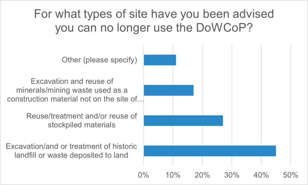
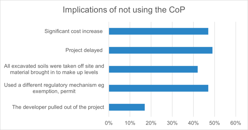
Over the last three years half the respondents reported being told by the EA they could no longer use DoWCoP for projects they would previously have done so (Graph 1) with the main reason being cited as development of historical landfills. One respondent indicated that personal discussions with EA Area Officers has clearly shown that Area Officers are also frustrated.  They can often see environmental benefits and gains from a proposal that they are told is no longer in line with EA national thinking on the use of DoWCoP.  One QP responded “It is not always going to be acceptable to reuse material from a historical landfill, or a stockpile, these are site specific decisions and often, will not be straight forward.  Rather than a blanket, include or don’t include in DoWCoP, each case should be considered in terms of its Conceptual Site Model.”

Graph 1

While the position for historical landfills is understood not to have yet been formalised the following footer is now appearing on some emails from the EA permitting team “The Environment Agency considers that any material which consists of current or historically landfilled waste remains waste on excavation and therefore cannot be used under DoWCoP.  Excavated landfilled waste materials require appropriate waste controls such as an environmental permit for storage, treatment and deposit.”  Whilst this position is now being circulated, there is limited steer or guidance on specifics such as what constitutes a current or historically landfilled waste, which could again be subject to interpretation.  In addition, consultants have recently reported changes in position within the EA on how sites are to be regulated mid-way through projects.    

30% of respondents had obtained an environmental permit to permanently deposit waste on land as a recovery activity (also referred to as deposit for recovery or DfR for short) in the previous 18 months. The time required to obtain the permit varied with 8% (five) of permits issued in six months or less, average was between 18 months to 2 years, with some reported as five years. Two refusals were reported after 3 years of consultations.

Major benefits of using the DoWCoP compared to a DfR permit are considered to be the reduced time and costs taken to prepare the Material Management Plan and submit the declaration. Where DoWCoP has not been used to support development our survey respondents reported significant cost increases, project delays and worryingly a trend towards the requirement to landfill material off-site and importing virgin aggregates to make up levels (Graph 2). Almost 1 in 5 projects were abandoned because the increased costs and delays to programme. 80% of respondents consider the exclusion of landfills, mining wastes and stockpiles from DoWCoP would hinder brownfield development. Some commonly expressed views were that their exclusion seems arbitrary and would hinder sustainable materials management for no economic, social or environmental benefit. Respondents also acknowledged that there needs to be effective regulatory oversight, particularly with landfilled wastes. Excluding landfills is considered counterproductive to the drive for sustainability and adoption of circular economy principles, leading to superfluous use of virgin materials, which result in the additional use of earth’s resources, increased carbon expenditure from additional transport of materials, impact on the utilisation of key landfill space.  Regeneration of landfill sites can have considerable positive impact on the social value of an area and short term potential negative impacts during redevelopment need to be managed.

Graph 2

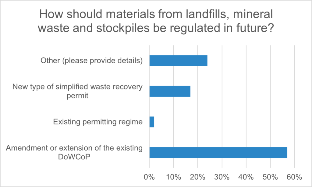
There is a significant view from respondents that the DoWCoP should be extended to cover development of landfills and materials from former mining activities including old stockpiles (Graph 3). The existing permitting regime has few advocates within the industry with some calls for a simpler (quicker) standard rules waste recovery permit.

Graph 3

There were also calls to modify the definition of waste to exclude materials for which there is a defined use. The review of legislation since Brexit offers an opportunity to rethink how waste is classified and material is reused within the UK in accordance with circular economy, sustainable development and net zero principles.

Conclusions

There is an increasing trend from the EA to require an environmental permit (deposit for recovery) to manage the reuse of material on development sites (historic, current landfills, stockpiles, possible mining extractive waste etc). The EA does not have capacity within the permitting system to accommodate this increase.  Permit decision times of greater than 6 months will not work in the construction sector. An increasing number of permits need to be bespoke because material for reuse and/or the environmental setting does not fit the standard rule permits available.

The DoWCoP has proved its worth to the brownfield development industry since its publication in 2008. It offers a simple cost-effective and crucially timely approach to managing the reuse of materials in construction. It also provides a pragmatic approach to the sustainable reuse of materials supporting the drive for circular economy, zero waste and enhancing social value all of which are key concerns in relation to brownfield regeneration.  The constraint to regeneration posed by the need to use the permitting regime is at odds with government drivers including brownfield first, recovery from Covid, levelling up and build back better. However, use of the DoWCoP has been inappropriate at times and as an industry we need to tighten up our understanding and application of it to regeneration.

Article provided by Clive Williams (Senior Associate Contaminated Land, Mott MacDonald), Louise Beale (Technical Director, SLR Consulting), Sarah Owen (Senior Associate, Waterman), Sarah Bullock (Associate Director, Atkins) and Catherine Copping (Technical Director, Stantec)


Article

AGS Award Winners 2023

- by
Tags: Featured

We were delighted to announce this year’s AGS Award and Commendation Winners at the AGS Annual Conference, held at the Barbican in London on the 27th April 2023.

Chosen from a select number of AGS Working Group Members, these Winners were all nominated by their Working Group Leader in testament to their hard work and dedication to the AGS over the past year.

A huge well done and thank you to the following Award and Commendation Winners:

AGS Loss Prevention Working Group

Chris Hoskins (Award Winner)

Hugh Mallett (Award Winner)

Zita Mansi (Commendation)


AGS Safety Working Group

Liz Withington (Award Winner)

Adam Latimer (Award Winner)


AGS Geotechnical Working Group

Emma Cronin (Award Winner)

Katharine Barker (Commendation)


AGS Data Management Working Group

Tony Daly (Award Winner)


AGS Contaminated Land Working Group

Angela Haslam (Award Winner)


To view the montage of acceptance speeches from our Winners, just click on the video below.


News

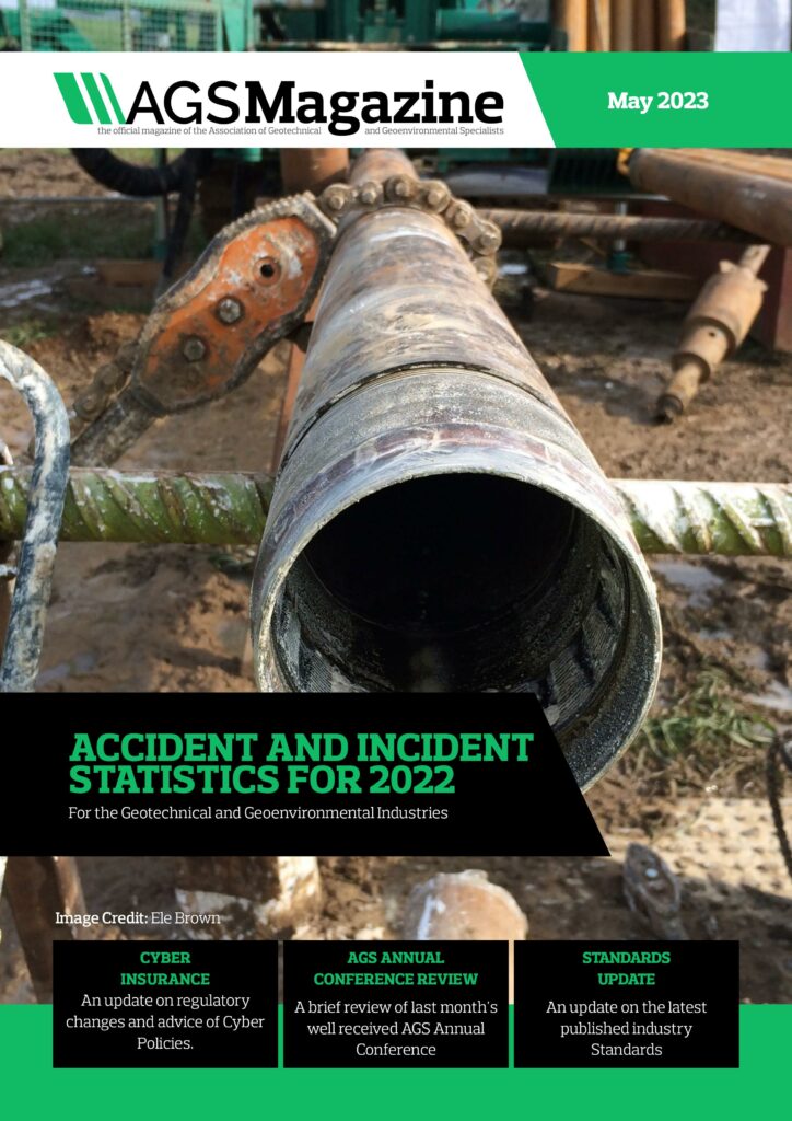
AGS Magazine: May 2023

- by
Tags: Featured

The Association of Geotechnical and Geoenvironmental Specialists is pleased to announce the May 2023 issue of their publication; AGS Magazine. To view the magazine click here.

This free, publication focuses on geotechnics, engineering geology and geoenvironmental engineering as well as the work and achievements of the AGS.

There are a number of excellent articles in this issue including;

AGS Annual Conference 2023 Review – Page 10

AGS Ground Risk Conference: Are you Managing Risks or Taking Risks? – Page 12

Geotechnical & Geoenvironmental Industry Accident Statistics 2022 – Page 18

Cyber Insurance – Page 26

Standards Update: March 2023 – Page 28

Plus much, much more!

Advertising opportunities are available within future issues of the publication. To view rates and opportunities please view our media pack by clicking HERE.

If you have a news story, article, case study or event which you’d like to tell our editorial team about please email ags@ags.org.uk. Articles should act as opinion pieces and not directly advertise a company. Please note that the publication of editorial and advertising content is subject to the discretion of the editorial board.

Article Safety

Geotechnical & Geoenvironmental Industry Accident Statistics 2022

- by
Tags: Featured

Within the wider construction industry, the geotechnical & geoenvironmental industry has been criticised, sometimes for good reason, for a poor safety record. It is true that this industry has not had the level of investment that mainline construction enjoys and there is internal, and client led pressure to deliver cost effective practices that can sometimes slow safety improvement and at worst negatively impact it.

To quantify the safety performance of the geotechnical & geoenvironmental industry and provide a benchmark from which to measure improvement, the Association of Geotechnical and Geoenvironmental Specialists (AGS) requested all members to volunteer accident data for the past two years as part of the annual members survey. From the members, an above statistical threshold (twenty-one) of twenty-seven organisations provided data.

How do the two industries compare?

Applying Health and Safety Executive (HSE) frequency and incident rate formulas to allow benchmarking against the HSE published Construction Statistics in Great Britain 2022, a direct industry comparison can be made.

From the HSE data, a construction workforce headcount of 2,048,611 can be identified, and a 2022 construction industry Accident Incident Rate (AIR) of 239.28, (35 fatalities + 4,185 non-fatal accidents / workforce) x 100,000 = 239.28.

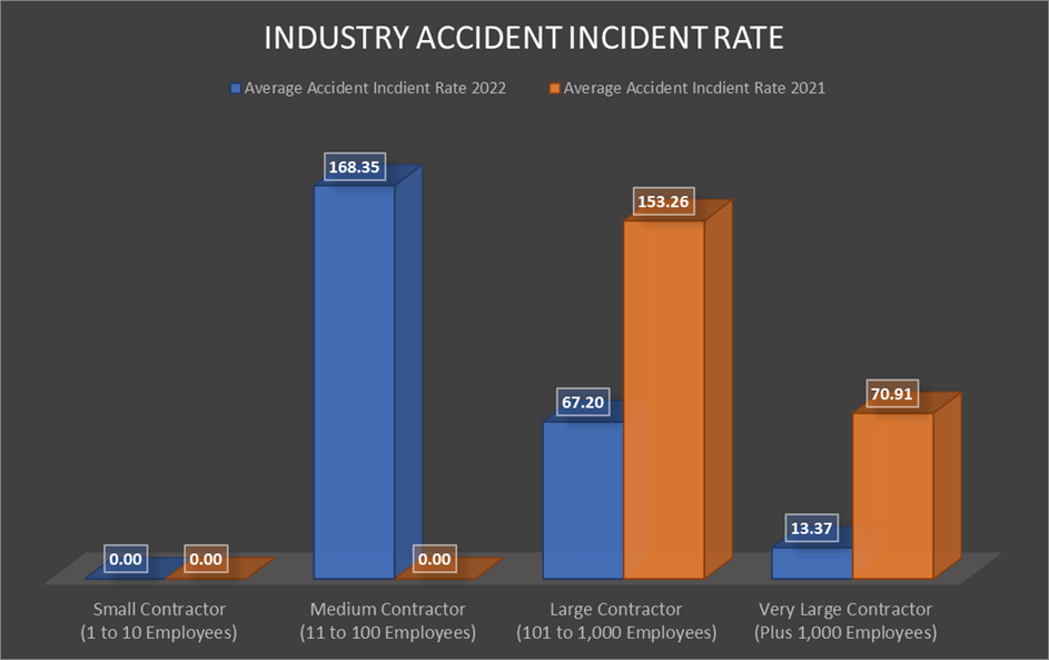
In comparison the geotechnical & geoenvironmental industry (from the data provided) has an AIR of 31.28 in 2022 and 81.63 in 2021. On face value, an AIR seven times lower than the construction industry could be celebrated, however the wider picture needs to be examined before the bunting comes out.

While some activities within the geotechnical & geoenvironmental industry are high risk, such as the person plant interface during drilling activities and underground utilities, the exposure to many additional high-risk construction hazards are limited, such as working from height, confined spaces, lifting activities, etc. Therefore, a like for like comparison with construction provides little value, as the risk profiles differ vastly. Yes, drilling is a hazardous operation, but it is only one element of the geotechnical & geoenvironmental industry, and yes, the construction industry does consist of many low risk tasks, but these are surrounded by other high risk activities.

What can the data tell us?

The real value within the data can be seen when we start to look at how different size organisations compare to each other and by setting a benchmark for subsequent years incident data to be measured against.

Before looking at the incident data by organisation size, it can be assumed that small organisations have less incident reporting processes than larger organisations, as it is not needed, organisational leaders have line of sight of the incidents and can document them. Likewise, it is less likely for a small organisation to formally record hazardous events, as they are seen first-hand, and these is a much smaller group to share information with, word of mouth is sufficient.

Likewise larger organisations have tried and tested systems, with dedicated safety professionals, supported by supervisors and managers to ensure that all incidents are reported, and hazardous events recorded, with learning shared across the workforce.

The organisations which can sometimes be weaker in incident reporting, incident management and incident learning are the medium size organisations. This is dependent on the time they have been operating in this space and particularly affects small organisations which have experienced rapid growth, with little time to implement improvements in their incident management and learning.

Within organisations with smaller headcounts a single RIDDOR reportable accident can have a significant impact on their AIR. As an example, organisations within the medium contractor group, with a combined head count of 594 has recorded one accident, resulted in an AIR in 2022 of 168.35. Compare this with a single accident recorded by large organisations in the same year produces an AIR of 67.29. To produce benchmarkable AIR targets an average is required across a longer sample period, as our group size is relatively small.

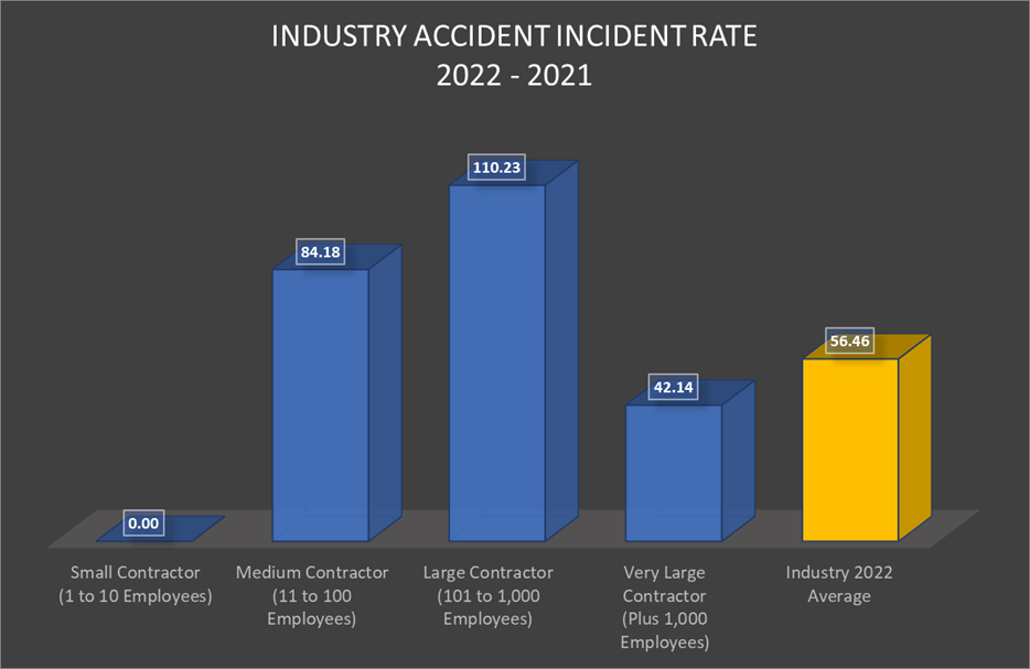
The above chart details the average AIR across two years for each organisation size, which is a better demonstration of the performance of the different size organisations, together with an overall industry average. This allows comparison against similar organisational performance and future safety improvement within the industry as a whole.

When examining the small and medium contractor accident data, 39% of organisations did not record any accident, near misses or hazard events over the two-year period, highlighting a poor reporting culture and indicating a potential higher AIR than 0.00 for small and an increased rate for the medium contractors than is shown.

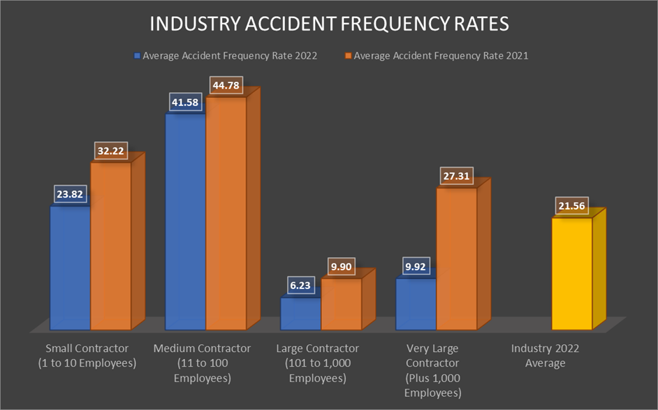
The Accident Frequency Rate ((AFR) total injuries / hours worked x 1,000,000)) provides a better indication of overall safety performance, as the rate is inclusive of minor injuries as well as RIDDOR reportable, which can sometimes be under reported.

Like the AIR, with 39% of small and medium contractors recording no accident data, the AFR for small and medium sized contractors could be significantly higher than detailed. This is a clear area of improvement for the industry, both in improving accident reporting and record keeping by the small and medium sized organisations and targeting these small sized organisations to develop safer working practices which will reduce harm.

The AFR across all organisations remains relatively close within 2022, ranging from 6.23 to 41.58 and an overall geotechnical & geoenvironmental industry AFR of 21.56. This provides a useful benchmark for the industry and individual organisations to measure their performance against.

Going further, to look at industry accident and incident reporting culture, the data needs to be compared with a suitable reporting frequency model. The original “accident pyramid” published by Herbert Heinrich in 1931 found that in a grouping of 330 similar accidents, one will result in serious injury (fatality, disability, lost time, medical treatment), 29 will result in minor injury (first aid), and 300 will result in no injury. Comparing industry data to an accident frequency model like this provides awareness of industry culture, as the model has been tried and tested, it is relevant. But is there a better model to use?

Looking at more recent studies there are two which go further. In 1969, Frank E. Bird conducted a follow-up study using a larger, more-randomized sample size (1,753,498 accidents). Bird found a ratio of one serious injury for every 10 minor injuries, 30 property-damage accidents, and 600 near-miss safety incidents. Due to the rigor of the study, this 1-10-30-600 ratio was accepted as an archetypal ratio in occupational health and safety.

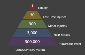
The most recent major study of the safety ratio was undertaken by ConocoPhilips Marine in 2003. It placed the Safety Triangle within a modern occupational context and found that for every single fatality there are at least 30 lost workday cases, 300 minor injuries, 3,000 near misses (estimated), and 300,000 behaviours not consistent with proper safety procedures (estimated). Aligned to the advancements in safety delivery from 1969 up to 2003, this model is more suited to today’s standards.

From this comparison several statistical features can be observed.

Firstly, looking at the relationship between lost time injuries and fatalities it can be suggested that every 7.5 years a person working in the industry will lose their life to a workplace accident. Although not measurable over a single time period, over 37.5 years the average of 1 fatality every 7.5 years would be correct, providing there is no changes to the current working practices, and no course change between now and 2060.

The relationship between minor accident and lost time accident reporting rates statistically holds up to the ConocoPhilips Marine triangle. As these are harm accidents, it is common for these to be the most robustly reported, as following first aid administration, the first aider has a duty to report.

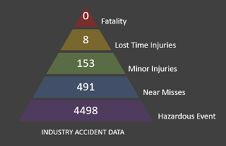
Looking down the triangle from minor injuries, there are clear industry weaknesses within near miss and hazard reporting. The current industry near miss reporting rate is showing an under-reporting value of 39%, highlighting a need for improvement.

Focusing on hazard reporting, 57% of the contractors stated that as an organisation they did not record hazard events and this shows, although not to a sufficient level to bring the hazard report rate in line with our accident triangle model. If the 57% reported hazardous events and at risk behaviours at the same rate as those in the industry that do, a total value of 11,924 reports would be made against a target rate of 80,000. Ignoring such an uplift, the industry hazardous event reporting rate is at a dismal 5.6% against the statistical target.

Both near miss and hazard reporting are proactive tool which can be used to prevent accidents from occurring. An improvement across both near miss and hazardous event reporting, learning and communication of the learning, would significantly reduce the amount of people harmed because of working within the geotechnical & geoenvironmental industry.

While we can not benchmark our industry accident data against the construction industry effectively, what we can do is learn from those that have walked the well-trodden path before us, in this case the drive within the construction industry to promote the importance of near miss and hazardous event learning to prevent harm.

If the organisations within our industry invest in putting in systems to capture, learn from and communicate our near miss and hazardous event learning, as an industry we can drive down the industry accident rates and improve prevention. Ultimately, we can delay, with the desire to prevent, the once in a seven and half year fatality to our workforces, colleagues, and friends.

Author Note: The sharing of accident data by AGS members has allowed the collective data to be examined to identify what, as an industry, we should be focusing on to reduce harm to our members. Please continue to share this information as it is requested each year, so we track the progress of our industry and focus our efforts within the areas which will have the most impact.

Article provided by Jon Rayner, AGS Safety Working Group Leader