6PPD-quinone (6PPD-q) is a transformation product of the tyre antiozonant 6PPD and has been identified as the primary cause of acute coho salmon mortality in urban streams, creating significant ecological and regulatory concern (Tian et al., 2020; Peter et al., 2021). Due to its higher polarity and mobility, 6PPD-q readily leaches from tyre wear particles (TWPs) into stormwater, producing episodic contamination pulses that are acutely toxic to sensitive salmonids and potentially harmful to other aquatic organisms (Brase et al., 2023; Kolodziej et al., 2023). Concentrations in urban runoff and receiving waters are typically reported from low to tens of ng/L, with first-flush storm events generating short-duration peaks (Rossi et al., 2022; Kolodziej et al., 2023). Reliable detection is achieved using LC-MS/MS methods supported by rigorous QA/QC procedures, including isotope-labelled internal standards and inter-laboratory comparisons (Seiwert et al., 2022; Peter et al., 2021).
Regulatory responses are developing internationally. In the United States, preliminary aquatic benchmarks and assessments under the Toxic Substances Control Act (TSCA) are guiding monitoring and risk management (US EPA, 2023; USGS, 2024). In the United Kingdom, 6PPD-q has been prioritised within national hazard screening and catchment-based water quality programmes (Environment Agency Chief Scientists Group, 2025), while within the European Union REACH Annex XV restriction dossiers are evaluating hazards, exposure, and alternatives, potentially leading to restrictions on 6PPD use in tyres (Seiwert et al., 2022; Rossi et al., 2022).
Mitigation approaches focus on both source control and environmental management, including chemical substitution of 6PPD, tyre reformulation to reduce additive release, and stormwater treatment systems designed to capture TWPs before discharge to surface waters (Wagner et al., 2018; Kolodziej et al., 2023). Although human exposure is currently considered lower than ecological exposure, occupational and environmental pathways remain plausible, and the reactive quinone structure suggests mechanisms involving oxidative stress and immunotoxin effects that require further investigation (Zhang et al., 2024; US EPA, 2023).
Key messages for regulators and industry
- 6PPD-quinone is a mobile and acutely toxic transformation product strongly associated with stormwater-driven salmonid mortality and should be prioritised in environmental monitoring programmes.
- Effective risk management requires harmonised LC-MS/MS monitoring methods and targeted sampling of first-flush runoff events to capture peak exposures.
- Regulatory strategies should integrate precautionary source control, evaluation of safer alternatives, and stormwater mitigation while maintaining tyre performance and road safety.
- Introduction
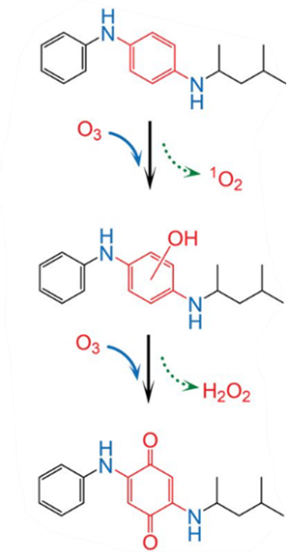
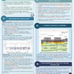
6PPD is a critical antiozonant in tyres, preventing oxidative degradation and thereby supporting tyre longevity and road safety (Kolodziej et al., 2023). However, tyre wear particles (TWPs) represent a significant diffuse source of chemical contamination in urban environments. During storage, on-road use, and following deposition, 6PPD reacts with ozone to form 6PPD-quinone (6PPD-q) (Figure 1), a reactive and bioactive quinone that is readily transported in aquatic systems (Kolodziej et al., 2023; Seiwert et al., 2022).

Figure 1 6PPD reacts with ozone to form 6PPD-quinone (Image with permission from Zhenyu Tian, Barnett Institute, Northeastern University, USA)
Acute ecological effects were first documented in the Pacific Northwest, where episodic coho salmon mortality events were linked to stormwater exposures at concentrations as low as 40 ng/L (Tian et al., 2020). Subsequent studies have demonstrated broader risks, including sublethal physiological and behavioural effects in multiple salmonid species and potential impacts on benthic invertebrates (Brase et al., 2023; Peter et al., 2021). Continuous TWP deposition onto road surfaces and into drainage networks creates pseudo-persistence in urban watersheds, even when individual storm events are transient, underscoring the need for routine monitoring and proactive risk management (Rossi et al., 2022).
Globally, regulatory frameworks are evolving in response to this emerging evidence. In the United States, 6PPD and 6PPD-q are being evaluated under toxic substances control act (TSCA) and state-level programmes; in the United Kingdom, they are being integrated into catchment-based water quality and chemical management initiatives; and in the European Union, several Member States are preparing REACH Annex XV restriction dossiers (Seiwert et al., 2022). This review provides an integrated assessment of 6PPD-q’s environmental occurrence, fate, toxicology, regulatory context, and risk management options, with the aim of informing aligned strategies for researchers, regulators, and industry stakeholders.
- Chemical Properties, Environmental Fate, and Toxicology
6PPD-q is a quinone derivative with higher polarity and water solubility than 6PPD, enhancing its mobility in aquatic systems and facilitating leaching from tyre wear particles (TWPs) (Kolodziej et al., 2023). Laboratory studies demonstrate rapid 6PPD transformation under environmentally relevant ozone concentrations (Seiwert et al., 2022), and field investigations detect 6PPD-q in urban stormwater, runoff, and surface waters at low to tens of ng/L, with pronounced peaks during first-flush events (Rossi et al., 2022; Kolodziej et al., 2023). Continuous formation and input create pseudo-persistence at the catchment scale despite attenuation through photolysis, microbial degradation, and chemical transformation processes (Wagner et al., 2018). However, environmental half-lives remain poorly constrained and are likely to vary with light, temperature, and redox conditions.
6PPD-q is highly toxic to salmonids. Coho salmon exhibit acute mortality at 40–90 ng/L, while rainbow trout mortality occurs at 200–300 ng/L (Tian et al., 2020; USGS, 2024). Sublethal effects include behavioural alterations, oxidative stress, and impaired disease resistance (Brase et al., 2023; Peter et al., 2021). Laboratory assays further report cardiotoxicity, gill damage, and endocrine disruption at environmentally relevant concentrations, underscoring episodic runoff as a serious ecological threat (Wagner et al., 2018). Emerging evidence also suggests potential impacts on benthic invertebrates and broader food webs, although effect thresholds and community-level consequences remain uncertain (Kolodziej et al., 2023; Seiwert et al., 2022).
Human exposure, while lower than aquatic exposure, may occur via dermal contact, inhalation of airborne TWPs, or ingestion of contaminated drinking water, with occupational exposure in tyre manufacturing, maintenance, and recycling settings considered the most significant (Zhang et al., 2024). The electrophilic nature of quinone compounds implies plausible mechanisms for oxidative stress, immunotoxicity, and genotoxicity, but chronic, human-specific toxicological data are limited (Zhang et al., 2024; US EPA, 2023).
Overall, convergence of laboratory evidence, field observations of episodic salmonid mortality, and emerging data on ecological and potential human health impacts supports designation of 6PPD-q as a priority environmental contaminant (Tian et al., 2020; Brase et al., 2023; Peter et al., 2021; USGS, 2024).
- Regulatory Status: United States, United Kingdom, and European Union
6PPD-q has gained regulatory attention due to its acute aquatic toxicity, environmental occurrence, and linkage to high-profile salmon mortality events.
United States: The US EPA has initiated processes under TSCA, including an Advance Notice of Proposed Rulemaking to collect additional data on 6PPD and 6PPD-q (US EPA, 2023). Preliminary aquatic life benchmarks, such as an 11 ng/L screening value for coho salmon, are being used to inform state monitoring and risk screening (Tian et al., 2020; US EPA, 2023). California has designated 6PPD a Priority Product under the Safer Consumer Products programme, triggering alternatives assessment requirements. Washington and Oregon have implemented stream monitoring to characterise episodic mortality and evaluate management interventions (Brase et al., 2023; USGS, 2024). Standardised LC-MS/MS methods, robust QA/QC, and inter-laboratory comparisons underpin TSCA Section 6 evaluations and local mitigation strategies (Kolodziej et al., 2023; Peter et al., 2021).
United Kingdom: 6PPD is registered under UK REACH without specific 6PPD-q restrictions, but TWPs are prioritised under the Chemical Strategy and Plan for Water. The 2025 Environment Agency Chief Scientists Group report identified 6PPD-q as a high-priority substance based on its acute aquatic toxicity and prevalence in stormwater (Environment Agency Chief Scientists Group, 2025). UK monitoring and risk prioritisation emphasise a systems-based, catchment-level approach that integrates 6PPD-q with other stressors, focusing on hazard screening and risk reduction rather than immediate substance bans (Wagner et al., 2018; Peter et al., 2021).
European Union: 6PPD is registered under REACH, and several Member States are preparing Annex XV restriction dossiers that evaluate hazard, exposure, socio-economic impacts, and technically feasible alternatives (Seiwert et al., 2022; Rossi et al., 2022). These REACH processes involve multi-year scientific review and stakeholder consultation and may ultimately result in use restrictions, substitution requirements, or product-specific risk management measures for 6PPD in tyres.
Across all jurisdictions, common regulatory principles include reliance on empirical toxicity data, standardised monitoring, and harmonised LC-MS/MS methods to support evidence-based action (Kolodziej et al., 2023; Peter et al., 2021). Key distinctions are that the United States emphasises federal–state coordination and provisional screening values, the United Kingdom focuses on catchment-based integration within broader water management, and the European Union relies on multi-stage REACH restriction processes with strong socio-economic analysis components.
- Analytical Methods, Human Health Risk, Regulatory Outlook, and Mitigation Strategies
Accurate detection of 6PPD and its transformation product 6PPD-quinone (6PPD-q) is essential for environmental risk assessment and evaluation of mitigation measures. Monitoring must account for the episodic nature of contamination associated with urban stormwater runoff, particularly first-flush events. Accordingly, both grab sampling during storm peaks and time-weighted composite sampling are used to capture maximum concentrations and integrated exposure profiles (Kolodziej et al., 2023; Peter et al., 2021). Samples are typically collected in amber glass or polypropylene containers to minimise photodegradation and sorptive losses and stored at low temperatures to prevent artefactual oxidation during transport and storage (Seiwert et al., 2022).
Analytical determination of 6PPD-q is predominantly performed using liquid chromatography–tandem mass spectrometry (LC-MS/MS), which provides the sensitivity and selectivity required for complex environmental matrices. Water samples are generally filtered and concentrated using solid-phase extraction, while sediments and tyre wear particles require solvent-based extraction methods such as ultrasonic or accelerated solvent extraction. Reversed-phase separation with electrospray ionisation and multiple-reaction monitoring enables detection at low nanogram-per-litre levels, with isotope-labelled internal standards used to correct for matrix effects and extraction losses (Peter et al., 2021; Seiwert et al., 2022). Robust QA/QC procedures, including blanks, matrix spikes, duplicates, and inter-laboratory comparisons—are necessary to ensure reliable data (Wagner et al., 2018). In the UK, the Environment Agency has emphasised the need for harmonised analytical methods for tyre-derived contaminants to support regulatory prioritisation (Environment Agency Chief Scientists Group, 2025).
Although ecological toxicity currently dominates concern, potential human exposure pathways include inhalation of airborne tyre wear particles, dermal contact with tyre dust, and ingestion of contaminated drinking water, with occupational exposure representing the highest risk (Zhang et al., 2024; US EPA, 2023). Toxicological data remain limited, but the redox-active properties of quinones indicate potential mechanisms involving oxidative stress and protein adduct formation. This lack of chronic toxicity data introduces uncertainty in human health risk assessment and highlights the need for further targeted studies (Peter et al., 2021; Kolodziej et al., 2023).
Regulatory attention to 6PPD-q is increasing internationally. In the United States, ongoing TSCA evaluations may lead to reporting requirements or use restrictions (US EPA, 2023; USGS, 2024). In the United Kingdom, the Environment Agency’s Chief Scientists Group has prioritised 6PPD-q for monitoring and integration into catchment-based management frameworks (Environment Agency Chief Scientists Group, 2025). Within the European Union, potential REACH Annex XV restriction dossiers may result in use limitations or substitution requirements following regulatory review (Seiwert et al., 2022).
Mitigation strategies focus on both source control and environmental interception. Source-based measures include substitution of 6PPD with less hazardous antiozonants and tyre reformulation to reduce additive release (Kolodziej et al., 2023; Wagner et al., 2018). Downstream controls aim to capture tyre wear particles before they enter surface waters through stormwater management systems such as bioretention, sedimentation basins, constructed wetlands, and advanced filtration (Rossi et al., 2022; Seiwert et al., 2022). In the UK, catchment-scale approaches, including targeted road sweeping, green infrastructure, and runoff attenuation, are increasingly considered practical methods for reducing contaminant pulses during rainfall events (Environment Agency Chief Scientists Group, 2025).
- Conclusions
6PPD-q is an emerging contaminant of ecological concern due to its acute toxicity to salmonids and pseudo-persistence in urban stormwater systems (Tian et al., 2020; Brase et al., 2023; Kolodziej et al., 2023). Standardised analytical methods, particularly LC-MS/MS with rigorous QA/QC, are critical for reliable monitoring and risk assessment (Seiwert et al., 2022).
Regulatory frameworks are diverging yet convergent in principle: the United States is advancing TSCA evaluations and state-level screening benchmarks; the United Kingdom is prioritising catchment-based monitoring and systems-level integration; and the European Union is progressing via REACH Annex XV restriction dossiers (US EPA, 2023; Environment Agency Chief Scientists Group, 2025; Seiwert et al., 2022). Human exposure, while currently considered limited relative to ecological exposure, warrants precautionary management given mechanistic concerns and data gaps (Zhang et al., 2024).
Mitigation requires integrated strategies combining chemical substitution, tyre reformulation, stormwater treatment, and catchment-scale management. Coordinated international efforts that align monitoring, research, and regulatory action will be essential to safeguard aquatic ecosystems while maintaining tyre performance and the resilience of urban infrastructure.
References
Brase, L., Kolodziej, E.P., Wagner, S., Peter, K.T. and Rossi, L., 2023. Ecotoxicological impacts of 6PPD-quinone on salmonids and aquatic ecosystems. Environmental Toxicology and Chemistry, 42(7), pp.1560–1574.
Environment Agency Chief Scientists Group, 2025. Hazard Screening and UK Risk Prioritisation for Tyre Additives. Environment Agency, UK.
Kolodziej, E.P., Seiwert, B., Peter, K.T. and Wagner, S., 2023. Environmental fate, transformation, and monitoring of 6PPD-quinone in urban runoff. Science of the Total Environment, 872, p.162021.
Peter, K.T., Kolodziej, E.P., Brase, L. and Seiwert, B., 2021. Analytical and toxicological assessment of 6PPD-quinone in aquatic systems. Environmental Science & Technology, 55(14), pp.9823–9836.
Rossi, L., Wagner, S. and Kolodziej, E.P., 2022. Tyre wear particles as sources of 6PPD-quinone in urban watersheds. Water Research, 224, p.118781.
Seiwert, B., Kolodziej, E.P. and Peter, K.T., 2022. Analytical methods for 6PPD and 6PPD-quinone detection in environmental matrices. Journal of Chromatography A, 1672, p.462975.
Tian, Z., Bruijns, R., Peter, K.T. et al., 2020. A ubiquitous tire rubber-derived chemical induces acute mortality in coho salmon. Science, 371(6525), pp.185–189.
US Environmental Protection Agency (US EPA), 2023. Advance Notice of Proposed Rulemaking for 6PPD and Transformation Products under TSCA. US EPA, Washington, DC.
US Geological Survey (USGS), 2024. Monitoring and assessment of 6PPD-quinone in urban streams. USGS Scientific Investigations Report 2024–5074.
Wagner, S., Rossi, L. and Kolodziej, E.P., 2018. Mitigation strategies for tyre-derived contaminants in stormwater and receiving waters. Environmental Pollution, 241, pp.1138–1149.
Zhang, Y., Peter, K.T. and Kolodziej, E.P., 2024. Human exposure pathways and preliminary risk assessment of 6PPD-quinone. Journal of Exposure Science & Environmental Epidemiology, 34, pp.221–233.
Article provided by Ken Scally¹,2
¹Normec DETS and Latis Scientific Laboratories, UK, 2Mount Royal University, Calgary, Canada