Article by Kalisha Sejpar (Associate, Ramboll)
At its core, Social Value is about maximising the positive impact that buildings, places and infrastructure have on society. It goes beyond just completing a technically sound project; it considers how that project contributes to local communities, the environment, and the economy in a meaningful way.
Social Value has become a crucial aspect of the engineering and construction industries in recent years, shaping the way projects are designed, delivered, and measured. However, its principles and applications are not well recognised across the majority of the ground engineering sector.
This article addresses some of the most common misconceptions about Social Value, providing clarity on what it means, why it is important, and how professionals in our industry can integrate it into their work.
Myth 1: “Social Value only applies to public contracts”
One of the most common misconceptions about Social Value is that it is only relevant for public sector contracts. This belief stems from the early adoption of Social Value policies in public procurement, such as the Public Services (Social Value) Act 2012, where the government first set out expectations for procurement decisions to take into account wider social, economic, and environmental impacts. The Social Value Model was then legislated in 2020, as outlined in Procurement Policy Note PPN 06/20, which solidified the commitment to embedding social value into the award of public sector contracts, assigning a minimum 10% weighting to it in tender evaluations. Social Value has since become an essential consideration for public sector clients, policymakers, and communities.

However, many private sector organisations are increasingly adopting Social Value principles voluntarily, driven by shifting public expectations, stakeholder pressure, and a desire to demonstrate corporate responsibility. While there may not be a legal mandate for private sector organisations to deliver Social Value, developers and investors are recognising the long-term benefits of integrating Social Value into their projects
For businesses, embracing Social Value is not only an ethical choice but a competitive one, as it helps improve reputations, build trust, and ultimately, win work across both public and private sectors.
—————-
Myth 2: “Social Value is just about STEM and job creation”
While STEM outreach and job creation are an important aspect of Social Value, they are just pieces of the puzzle. Social Value encompasses a much wider set of themes, enabling a range of social, economic, and environmental impacts. This can include enhancing physical and mental well-being, delivering environmental benefits, fostering diversity and inclusion, supporting SMEs (Small and Medium-sized Enterprises) and VCSEs (Voluntary, Community and Social Enterprise), improving educational and training opportunities, and engaging in co-design and delivery with communities. These are all critical components of Social Value that address the broader needs of communities, the environment, and society at large.
The broad scope of Social Value offers opportunities for a wide range of businesses and professionals to contribute. Contractors, consultants, and suppliers alike can integrate Social Value into their operations through various means. Social Value is also not limited to large businesses or those with specific expertise; it can be embedded into everyday practices across the supply chain, enabling businesses of all sizes to make a meaningful contribution.
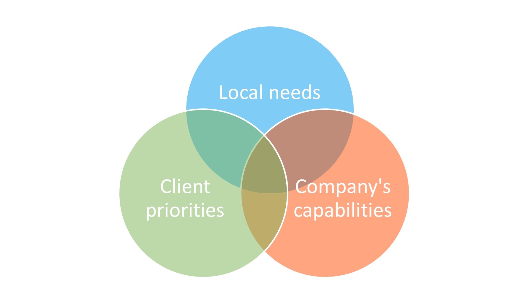
The exact social value that a project delivers will depend on the needs of the local community and the priorities of the client. Social Value should be tailored to the people most impacted by the development, with outcomes defined based on local needs and the specific context of the project. This means that Social Value is not a one-size-fits-all solution; rather, it must be relevant and meaningful to the community in which the project takes place, focusing on the issues that matter most to those directly affected.
—————-
Myth 3: “Designing/ building a hospital or school counts as our Social Value”
Another common misconception is that simply contributing to the construction of projects such as hospitals or schools automatically counts as delivering Social Value.
A fundamental principle to recognise is that Social Value involves creating additional value beyond the intrinsic value that is inherently tied to fulfilling the primary purpose of a contract. So, although the creation of a school or hospital can be a significant step towards improving communities’ access to education and healthcare, Social Value goes beyond merely providing infrastructure. It’s about embedding positive, additional impacts throughout the project’s lifecycle, adding social, environmental, and economic benefits that extend beyond the primary objective.
This concept can be broken down into three distinct categories:
Inherent Social Value relates to the direct and primary impacts that an activity or contract delivers as part of its core purpose. For example, providing health services through the construction of a hospital is an inherent benefit, directly contributing to the community’s healthcare needs.
Embedded Social Value typically involves an organisation’s ‘business as usual’ activities that contribute to social value, typically delivered through practices like apprenticeship schemes, environmental policies and supply chain engagement. For example, sustainable supply chain practices, such as sourcing materials from local suppliers to reduce carbon emissions and support local economies.
Additional Social Value goes beyond both inherent and embedded value and involves intentionally creating extra, measurable societal benefits that are not an intrinsic part of the core service. For example, encouraging staff to volunteer in community projects, like creating a green space local to the hospital site.
When delivering Social Value through contracts, Inherent Social Value cannot be claimed, however Additional Social Value, and where appropriate Embedded Social Value, can be claimed, but only for the tangible benefits that arise directly from the contract in question.
—————-
Myth 4: “We already do CSR, so we’re delivering Social Value”
Corporate Social Responsibility (CSR) reflects a commitment by businesses to operate responsibly, ensuring they adhere to ethical standards and hold themselves accountable for their actions. CSR is primarily voluntary and self-regulatory. It predominantly revolves around internally focused initiatives within business operations, with strategies often self-determined, guided by an organisation’s own priorities rather than being shaped by the needs of a particular community, client, or contract. CSR activities can be valuable, but they do not necessarily meet the criteria for Social Value especially as they often comprise one-off endeavours that do not necessarily occur where contracts are being delivered. However, where relevant, they can contribute to Embedded social value.
Social Value, by contrast, is contract-specific, locally focused, and embedded into the delivery of a project or service. It requires organisations to consider how they can maximise tangible, lasting benefits for the communities directly affected by their work.
For example, an organisation may have a CSR initiative that funds tree planting in various locations nationwide. While beneficial, it’s a broad, self-directed effort. In contrast, to deliver Social Value on a local infrastructure project, the organisation can plant trees in nearby urban areas, working with local schools to educate students on biodiversity and climate resilience. This ensures the impact is place-based, directly benefiting the local community and aligning with project-specific goals.
The key distinction therefore is that Social Value is an integrated and accountable part of project delivery, not just a standalone corporate initiative.
—————-
Myth 5: “Social Value is not my responsibility – someone else will deal with it”
Social Value is everyone’s business. Regardless of role, sector, or project stage, all professionals involved in the built environment—including geotechnical and geoenvironmental specialists—have a part to play in delivering meaningful benefits to society.
Social Value is not limited to those in client-facing roles or those directly involved in community engagement, or on-site construction – it is relevant to all services including consultancy, design, investigation, and construction, and applies equally to those conducting early-stage desk studies as to those delivering on-site groundworks.
Social Value can take many forms across the geotechnical and geoenvironmental sector. Some examples include:
- Contractors working in an economically deprived area can create targeted employment and training opportunities for local workers from disadvantaged backgrounds;
- Consultants can share findings on geotechnical hazards or contamination risks with local communities, helping to raise awareness of climate resilience and environmental sustainability, and helping communities feel more connected to the development process;
- Contractors can minimise environmental disruption by adopting low-carbon ground improvement techniques, sourcing locally sourced materials and implement construction practices that minimising noise;
- Consultants can implement solutions that minimise soil disturbance, allowing for the preservation of trees and green areas, which supports biodiversity and provides space for community activities;
- Consultants and contractors can volunteer time for example restoring local wetlands, or providing technical advice on local geotechnical or geoenvironmental hazards, involving residents and improving overall community wellbeing
While some of these outcomes are often by-products of good engineering practice, there is now a growing expectation—from governments, clients, and the public—that they be planned, measured, and maximised.
Embedding Social Value into projects is not about reinventing roles as professionals but rather being intentional about maximising positive outcomes.
—————-
Myth 6: “There’s no contractual commitment to Social Value”
Another common misconception is that Social Value commitments made during tender are not enforceable and that there are no real consequences for failing to deliver them. However, this is increasingly not the case. Clients, both public and private sector, are strengthening their approach to Social Value by integrating mechanisms into contracts.
For example, many contracts include performance monitoring, with Social Value within Key Performance Indicators (KPIs). This means that not delivering on your commitments can lead to removal from the project/framework and significant reputational damage. Others go further by enforcing financial penalties for non-delivery.
Going forwards, under the Procurement Act 2023, contracting authorities will have greater flexibility to assess supplier performance over time, meaning that failure to embed and deliver Social Value could lead to exclusion from future contract opportunities. Similarly, government guidance for the new Social Value model is to include all social value commitments in the contract either as contract terms, key performance indicators, or performance indicators.
With growing scrutiny, businesses must take Social Value commitments seriously. This requires moving beyond vague promises and ensuring that measurable, meaningful outcomes are delivered and performance evidenced at regular intervals throughout the contract lifecycle.
—————-
Myth 7: “It’s all about maximising SROI”
There is a common misconception that Social Value is primarily about achieving the highest possible Social Return on Investment (SROI) or maximised financial figures. While monetisation can be a useful tool in measuring Social Value, it is not the sole focus.
Social Value measurement frameworks and reporting tools such as TOMs (Themes, Outcomes and Measures) system have been developed to provide structured methodologies; some of these frameworks include financial proxies—assigning a monetary value to social impacts to help quantify their relative importance. However, this approach, while useful for benchmarking and comparison, does not capture the full picture of Social Value.
A growing concern is the tendency to focus too heavily on headline financial figures, leading to what some refer to as “social value washing”—prioritising impressive-looking numbers over meaningful, long-term impact. This trend mirrors similar challenges seen in other sustainability fields, such as carbon reduction, where measurement frameworks sometimes overshadow the real objective. Social Value should not become a numbers game but should remain centred on genuine, place-based benefits that create lasting change.
Ultimately, Social Value is about people, not just numbers. To ensure genuine impact, organisations must look beyond financial figures and focus on creating meaningful, measurable, and lasting change within communities.
—————-
Bonus Myth: “Social Value is just a passing trend”
Despite international trends where some governments prioritise economic growth over strong social policies, the UK is taking a distinct approach—embedding Social Value as a core part of procurement strategy rather than treating it as a passing trend.
With the Procurement Act 2023 shifting procurement decisions towards selecting the “most advantageous tender”—rather than simply the “most economically advantageous”—Social Value is becoming even more integral to procurement strategies.
The National Procurement Policy Statement (NPPS) reinforces this commitment by prioritising the government’s missions in procurement, ensuring public spending delivers not just value for money but also tangible economic, social, and environmental benefits. The new Social Value Model requires that organisations bidding for public sector contracts actively contribute to these priorities, moving beyond simply meeting baseline contract requirements.
Therefore, with evolving legislation and increasing public demand, Social Value is here to stay and grow.
Social Value directly addresses the challenges facing our industry today, from workforce shortages and sustainability targets to inclusion and economic resilience. This presents a significant opportunity for organisations and individuals to play an active role in shaping positive outcomes. Whether through skills development, sustainable practices, or community engagement, think about how you can support Social Value objectives and advocate for these principles within your team to ensure they are embedded into everyday decision-making and project delivery.
References
PPN 002: https://assets.publishing.service.gov.uk/media/67ae1529e270ceae39f9e1a0/2025-02-11_PPN_002_The_social_value_model.docx.pdf