Cone Penetration Testing (CPT) or Piezocone (Cone Penetration with pore water pressure measurement (CPTU)) have seen a significant increase in use over the last 20 years. It has grown from a rarely used test to forming a significant element of most ground investigations carried out today. The publication of documents such as Eurocode 7 and ISO standard has helped push the use of CPTs as a reliable and important method of gaining quality repeatable in situ data from the ground for design purposes.
Developments in the cone technology allowing equipment to be more robust has also helped, along with the ever-increasing number of sensors that can be added to a CPT to make the test even more powerful.
Test Procedure
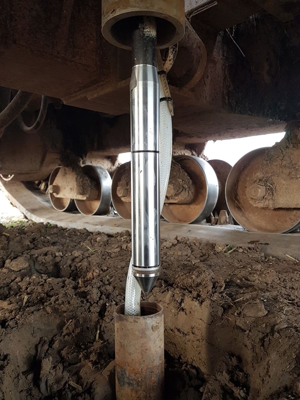
The test procedure is clearly defined in the British Standard, BS EN ISO 22476-1. In its simplest form, a cone is pushed into the ground at a standard penetration rate. The cone is connected by an umbilical cable that feeds the data to the data logger and logging computer, which displays these results in real time on screen. The cone is pushed in using a series of 1-metre-long rods by a set of hydraulic rams inside the CPT rig.
There are several checks and some preparation of the cone that needs to be done before commencement of the test which is outlined in the British Standard in detail. These include things such as checking the dimensions of the cone, checking zero values, being aware of temperature differences and saturating the piezo element of the cone.
The test is carried out at a relatively fast rate of two centimetres per second, when compared to traditional drilling techniques. This enables between 100 to 150 metres of testing in a shift, depending on ground conditions.
It is also vitally important to fully understand the limitations of CPTs. A standard CPT rod is only 36mm in diameter and most rigs will push between 10-20 tonnes, so care has to be taken not to damage or break the equipment. A good understanding of the probable ground conditions is vital when deciding if CPTs will give you the required outcome on your site.
CPT Equipment
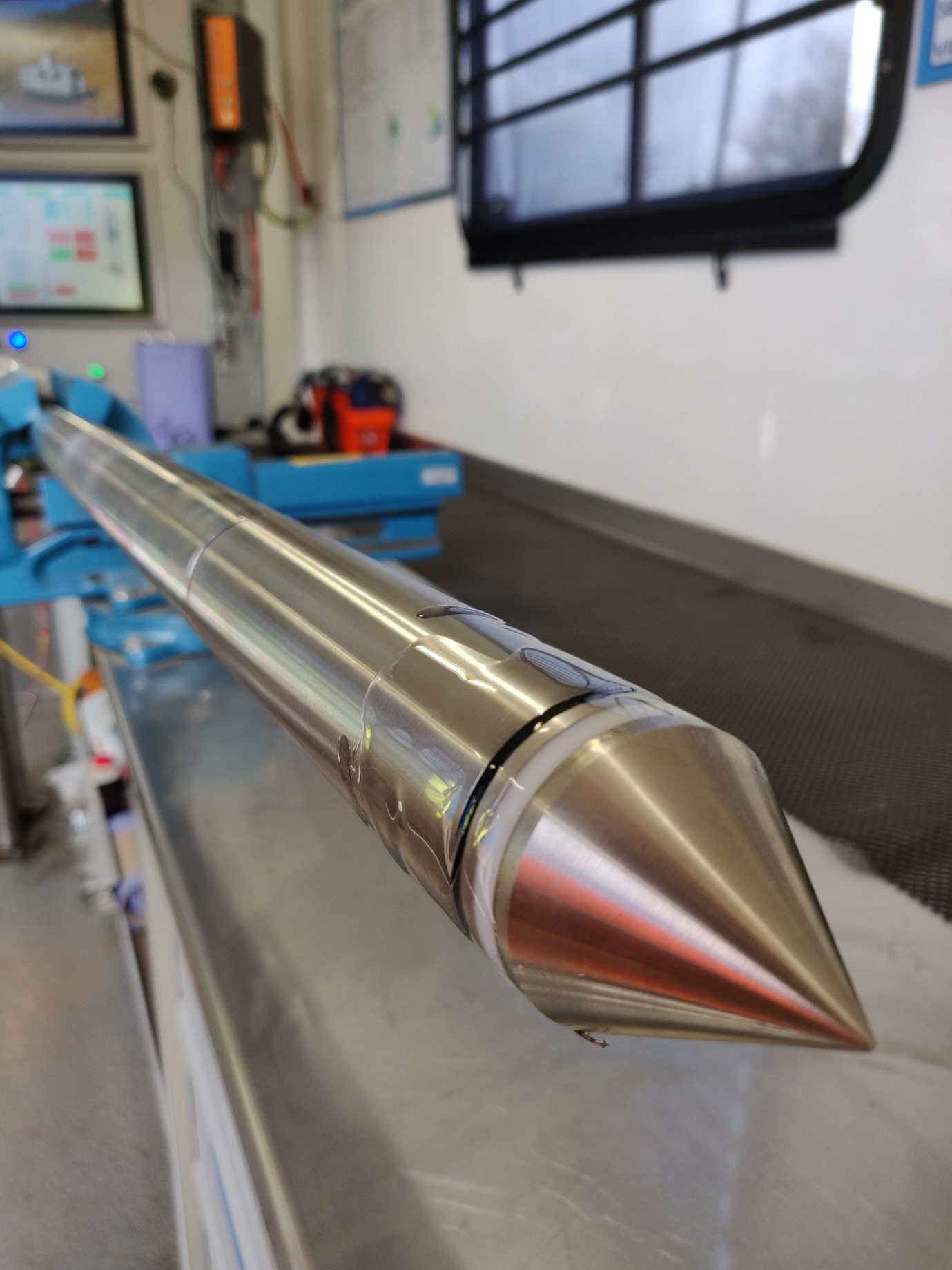
Cones
Cone technology has seen major developments over the past 20 years. The standard CPT cone now measures pore pressure and is referred to as a piezocone. The pore pressure element can also be mounted in one of three positions, depending on ground conditions and the purpose of the test. Over recent years, the importance of temperature effecting the electronics inside the cone has been recognised and this has led to better temperature compensation.
Cones have also moved from being analogue to digital, which has allowed for many more sensors to be added to a standard CPT to gain additional data. These include magnetometers for detecting unexploded ordnance and pile lengths; sensors that measure the natural gamma radiation in the soil which can assist in solution feature investigations and the seismic cone which can measure shear wave velocites down hole. A more detailed list is provided in Table 1.
There has also been a significant development in the application of environmental cones that are capable of measuring most types of contamination. Two common examples of environmental cones are the membrane interface probe and the optical imaging probe. These are used to rapidly map contamination plumes over large areas. A more detailed list of these cones are provided in Table 1.
Table 1. List of some of the different cones and modules commonly used.
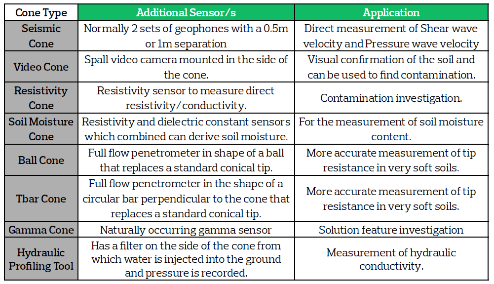
Other cone types that are regularly used are the soil moisture probe, video cone with a camera mounted on the side that records an image and the hydraulic profiling tool which pumps out water as the cone is going into the ground to measure hydraulic conductivity. There are also specialist cones for working in very soft soils. These can be specially calibrated CPT cones or modified cones such as the ball cone and T-Bar.
Cones are not the only thing a CPT rig can push into the ground! There are specially modified vanes that can be used to measure shear strength directly and driven sampling systems. The CPT rig can also be used for installing instrumentation such as piezometers and inclinometers.
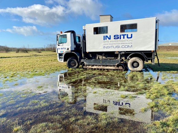
Rigs
CPT rigs come in all shapes and sizes depending on what is needed for each particular project. The larger the rig the more reaction weight it will have to push the cone in the ground. However, it is not always the case that you need a large rig to achieve the required depths in a certain ground condition. You also don’t always have the space for a large CPT rig so smaller ones may need be deployed instead.
Rigs are often divided into wheeled and tracked versions and these can come in different sizes. You can also get rigs that have both wheels and tracks on them, known as track-trucks. A good thing about the larger rigs is that they provide comfortable places for work not only for the CPT operator but also the supervising engineer.
Smaller CPT rigs such as crawlers can be between one and a half and three tonnes. These rigs typically come with some sort of anchoring system to provide extra reaction force for the test. The use of the anchors can slow down the overall operation and reduce the amount of testing that can be completed in a shift and consideration also needs to be taken for the potential to damage underground services, if used. The major advantage of these rigs is that they can be used to access difficult to reach locations and they are often used on Jack up platforms and pontoons for carrying out work over water.
There are even smaller rigs which are hand portable that are often used in basements. These are bolted to the concrete slab in the building which then provides the reaction force for the test. These can be run off an electric power pack which enables emission free testing inside a building with no need for fume extraction.
Furthermore, there are rigs that have been specially adapted for work in certain environments. The rail environment is a good example where rigs have been modified to fit on rail vehicles to enable testing to be carried out from the track.
Offshore is also a major area for CPTs and it is this industry that funded a lot of cone development research during the 1970s and 80s. The speed of the CPT and the quality of data that we get from it makes it ideal for work in marine environments. Rigs have been developed that are fully submersible which can be lowered to the seabed to carry out tests. Projects in this sector are commonly for pipeline routes and foundations for wind farms.
Data Processing
While performing a piezocone test, the measured data is automatically converted from millivolts to engineering units. The results of cone resistance qc, sleeve friction fs, and porewater pressure u2 are shown graphically on the computer screen, giving real time access to the interested parties. Inclination and penetration rate are also monitored; although they are not used directly in soil classification and geotechnical parameters derivation, they assist in the process of quality checking the data.
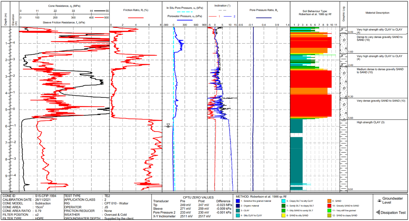
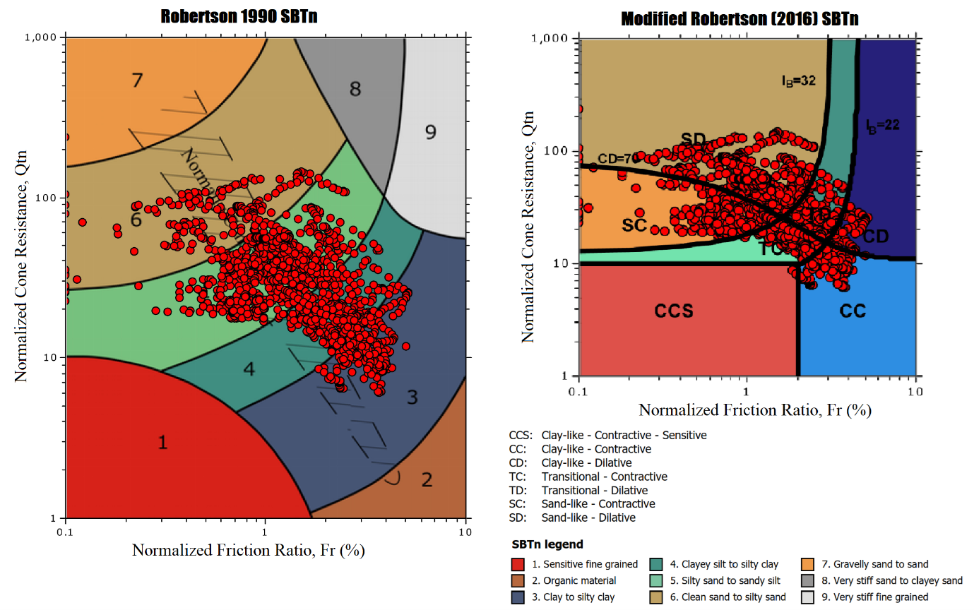
Data processing starts with generating the corrected cone resistance, qt and friction ratio, Rf through very simple calculations which involve measured results only. At this phase of data processing, Soil Behaviour Type, SBT can be plotted on one of the charts available based on qc/ qt and Rf to give a name to the soils encountered during penetration. To derive more soil properties, it is nearly always necessary to have information on groundwater conditions, GWL and density/unit weight, γ to establish total and effective vertical stresses, σv0 and σ’v, to derive pore pressure ratio, Bq and other normalized parameters, Qt and FR, which can be used to classify soils based on more advanced SBT charts, like Robertson 2016, which interpret soils strictly based on their behaviour (contractive or dilative, drained or undrained) instead of giving the geological descriptions (sand, silt or clay).
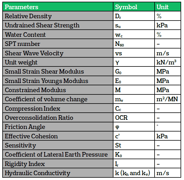
Furthermore, data processing continues with the derivation of geotechnical parameters based on many correlations published in the literature over the years linking the measured CPT/U data to the required soil properties. These correlations are incorporated into various software packages making it a very easy electronic process to plot the results on soil behaviour type charts and to generate all possible soils properties. However, the use of software to process CPTU results into geotechnical information should be done with care. Although these packages perform the mathematical calculations correctly, they are often used with too little basic information, experience and/ or knowledge (Powell & Dhimitri, 2022). A list of soil properties that can be derived from CPTU measured data is presented in Table 2.
Table 2. List of possible parameters to derive from correlations available in the literature.
Use of CPTs in Geotechnical Practice
CPTUs are a powerful tool not only for soil characterisation, but also to give extensive information on soil properties and their behaviour in situ. Over the years, they have proven to be very successful to provide information regarding the design parameters in difficult soil conditions. The use of CPTU tests is worthwhile in settlement evaluation, especially when you perform a dissipation test by stopping the penetration at the required depth and waiting for the excess pore water pressure to dissipate. This provides us with valuable geotechnical information such as ground water level at that position in that moment if the dissipation test is left to run to equilibrium, drainage conditions and consolidation parameters. Furthermore, measured or derived parameters from CPTs can be used to perform bearing capacity analysis for shallow and deep foundations.
CPTU based methods to assess the liquefaction potential (the phenomenon that turns solid ground into a liquid-like state) of soils are straightforward to determine the cyclic resistance ratio, CRR. They have proven to be very successful in tailings materials and regions prone to earthquakes. In addition, CPTUs are widely used as a quality check for ground improvement projects where cone resistance, qc pre and post ground improvement application helps the designers to make real time decisions. In areas where the geology is Chalk, cone penetration tests are becoming a cost-effective method to identify chalk and solution features, especially by taking measurements of the gamma radiation while penetrating the soils.
Reference
Powell, J. J. M., Dhimitri L. “Watch out for the use of global correlations and “black box” interpretation of CPTU data [taylorfrancis.com]”. 5th International Symposium on Cone Penetration Testing (CPT’22), 8-10 June 2022, Bologna, Italy. CRC Press. p. 651-656
Authors:
Darren Ward – Managing Director – In Situ Site Investigation Ltd
Luisa Dhimitri – Geotechnical Engineer – In Situ Site Investigation Ltd
John Holt – Pressuremeter Testing Manager – Senior Geologist, Insitu Testing