 Search
Horizontal directional drilling (HDD) is a form of trenchless crossing that is used to install utilities (e.g. power cable ducts and pipelines) beneath roads, railways, rivers and other sensitive land uses with minimal disruption compared with other forms of construction. It is an established technique with successful installations internationally as well as in the UK.
How does it work?
- Launching and receiving sites are established at the exit/connection points of the HDD installation.
- A pilot bore (typically 150mm dia) is drilled on a parabolic arc from one side to the other. The technique is fully steerable in the horizontal and vertical planes. For increased lengths, straight lengths can be incorporated within the overall drill profile. Depending on ground conditions, installation technique and site access, lengths of several km are possible.

- After the pilot drill has punched out at the exit pit, a back reamer is attached and pulled back through the drill shot to enlarge the bore. Various drilling fluids may be used including water, polymers and bentonite.

- Progressively larger reamers are utilised until the final bore size is achieved. Final bore diameters generally range from 6” (152mm) to 26” (660mm) but can be up to 48” (1219mm).
- Once the bore is at the required diameter the final duct(s) / pipe is pulled through the bore before being cleaned and temporarily capped at both ends. The duct(s) / pipe is then ready to be connected to the rest of the network, which is typically at a nominal depth (<1.2m).

Typical Parameters
The bend radius is a function of tooling used and pipe being installed. On small scale rigs in soft ground a radius as tight as 75m can be achieved whereas large diameter bores or rock tooling requires bend radii in excess of 400m. Plastic pipes require bend radii of 25 times outside diameter typically. In contrast thin walled steel pipes require a radius of 1000 times outside diameter.
The length of a drill shot can vary significantly but is typically 60 – 250m. Longer drills (several hundred metres) are possible and typically required for landfall projects where offshore cables join onshore networks. Drill lengths of 1 to 3 km are now becoming more commonplace.
The drill can bend in the vertical AND horizontal planes. If undertaking a compound bend (vertical and horizontal at the same time) then individual bend radii should be reduced so that the overall bend remains within tolerance.
Drilling fluid
Throughout the drilling process, drilling fluid or ‘mud’ is continuously pumped into the bore via the drill head / reamer primarily to stabilise the bore and transport cuttings back to the entry pit. The mud recipe and pump rate is critical to ensure a successful HDD:
- Too viscous means higher pressure required to move the cuttings, thereby increasing the risk of heave
- Too fluid and the bore may be unstable and subsequently manifest as excessive settlement.
- A mud mixture is site specific and tailored to the ground and groundwater conditions anticipated.
Key advantages of HDD
It is trenchless! Closing a motorway or railway to install a utility is often not a feasible option. Traverses below canals, rivers and subsea installations are also possible with this technology.
HDDs create very little disturbance at the surface. The entry pit is typically of the order of a few metres in length and width and a nominal 1m depth. The exit pit is usually similar unless there are significant elevation differences. The limited excavations have a notably less environmental impact than an equivalent trenching option.
Trenching often creates a soft line in the ground due to inadequate compaction during the backfill process, akin to trial pitting during a GI. This leads to ongoing settlement and possibly abrupt changes in surface level that could pose risks to users (e.g. drivers). In contrast, the settlement profile that may develop post HDD construction is generally much more gradual, if any movement is experienced at all, due to the ground being much less disturbed. Settlement of <5mm is common.
All HDD works are undertaken by personnel at the surface. This has clear safety benefits by eliminating the need for deep shafts or excavations that would be required for other trenchless techniques such as microtunneling
Key constraints of HDD
HDDs should not be considered a silver bullet and have two principal limitations: coarse ground conditions and space to string out the pipe / ducts.
The drilling process is versatile and can successfully drill through a variety of ground conditions including soft ground and rock. However, coarse ground conditions (coarse gravel and cobbles) can be particularly challenging. Bores in such ground conditions can be unstable, which causes further overbreak and potentially manifesting as increased settlement at the surface. The usual method of mitigating this issue is to install a casing through such ground conditions, akin to cable percussion drilling.
Boulders can also be problematic by causing the drill to deflect from the intended trajectory. It can sometimes be feasible to partially withdraw and then steer around the boulder. However, usual practice is to try again nominally offset from the issue – similar to cable percussion drilling!
The second limitation is associated with site practicalities. Only small diameter ducts can be transported to site on a reel. All other ducts and pipes require welding on site to create the pipe string. The length of the pipe string is equal to the length of the drill and therefore can be hundreds of metres long. There needs to be space on site to laydown the completed pipe string prior to pull back. Due to the flexibility of the pipe it can snake past obstacles while strung out as illustrated in Figure 1.
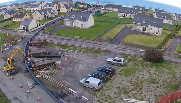
Figure 1: Example of pipe sting out prior to pullback
Steering – How accurate is it?
There are three ways of steering an HDD:
- Walkover locating using a radio sonde
- Magnetic wireline
- Gyro
The walkover as the name suggests involves a person with a hand held device receiving a signal that is transmitted from the drill head. This locates the drill head and allows steering adjustments to be made. Due to the walkover nature of the technique it is limited to simple low risk crossings.
The wireline system involves laying a surface tracking grid that emits an artificial magnetic field that the drill head uses to provide a precise location. A grid is often required on both sides of the crossing with the middle part effectively being ‘blind’ as the drill passes from one grid to the other.
The best form of steering is the Gyro, which has an accuracy of 0.01°. From previous experience on long drills (>200m) this can be considered to be centimetre accurate at worst. However, the high accuracy attracts a similar price tag and is therefore reserved for the long or complex drills.
What can go wrong?
A principal risk on all HDD projects is the frac out of fluids during drilling, which is intrinsically linked to surface heave. Frac out is ultimately due to the downhole pressure exceeding the confining pressure which results in fluid travelling upwards and eventually out at the surface. In the event of a frac out it should be contained (example below) and then cleared away.
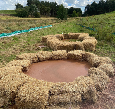
Figure 2: Example of surface frac out and subsequent containment
Excess pressure can be caused by:
- Collapse of the bore behind the drill head stopping the drilling fluid flushing the bore
- Cuttings remain in the bore due to insufficient fluid rate
- Incorrect drilling fluid recipe
- Heavily fractured or fissured ground conditions providing preferential pathways
Calculations can be undertaken with commercially available software to assess the risk of frac out. The risk is highest during pilot drilling due to the smaller annulus between the bore and drill pipe. The results should be considered guidance only and just because it suggests frac out will occur it doesn’t mean it will, and vice versa. There is often a risk close to the exit pit where drill pressures remain relatively high and cover thickness is minimal.
HDDs also have the potential to cause ground movement, which may manifest as settlement at the road surface or beneath existing buried utilities. Relatively simplistic formulae are used to estimate the long term settlement trough.
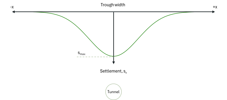
The size of the trough is a function of ground conditions and depth of cover. Cohesive soils produce wider troughs but a smaller maximum settlement (smax) when compared to non-cohesive soils. Similarly, installing the drill at greater depth reduces smax but widens the trough.
Early Contractor Involvement
Engaging early with a specialist contractor is highly recommended. The contractor can advise on the suitability of an HDD versus other techniques. This will likely include conceptual design to estimate length and depth of any drill. Consequently, they should also provide input into any ground investigation scope.
Article provided by Angus Wilson, Geotechnical Manager, AMS No-Dig