Pressuremeter testing (PMT) is a recommended insitu testing technique for ground investigation, referenced in Eurocode 7 (EN 1997-2). The objective of a pressuremeter test is to measure the Insitu-deformation of soils and rocks by the measured expansion of a cylindrical pressurised membrane (EN 1997-2).
These instruments are employed typically to provide insitu strength, stress and stiffness parameters of soils and rocks. This type of testing provides high quality information due to the minimised disturbance of the insitu ground state, particularly when compared to samples removed for geotechnical laboratory testing. Testing is carried out in accordance with the relevant sections of BS EN ISO 22476, depending on the type of pressuremeter deployed.
To achieve the desired parameters, all pressuremeter tests consist of an incremental increase and decrease of radial stress, acting on the material at the borehole wall. This varying radial stress is dictated by the pressure within the instrument itself, which is controlled by an operator at the surface.
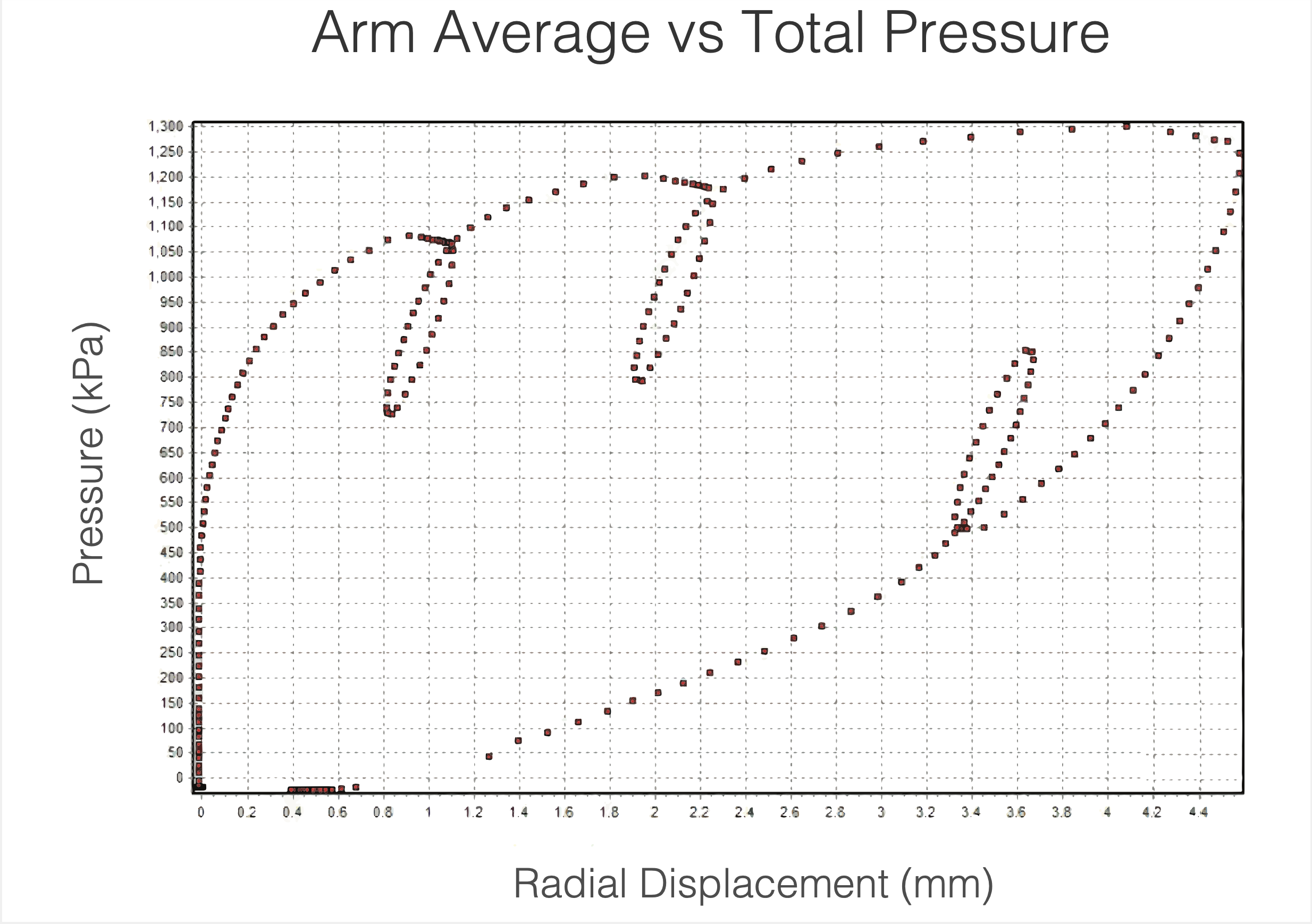
Figure 1. Graph showing the field curve of pressure vs displacement as produced by a digital direct strain measuring pressuremeter. Image by Cambridge Insitu Ltd, 2022
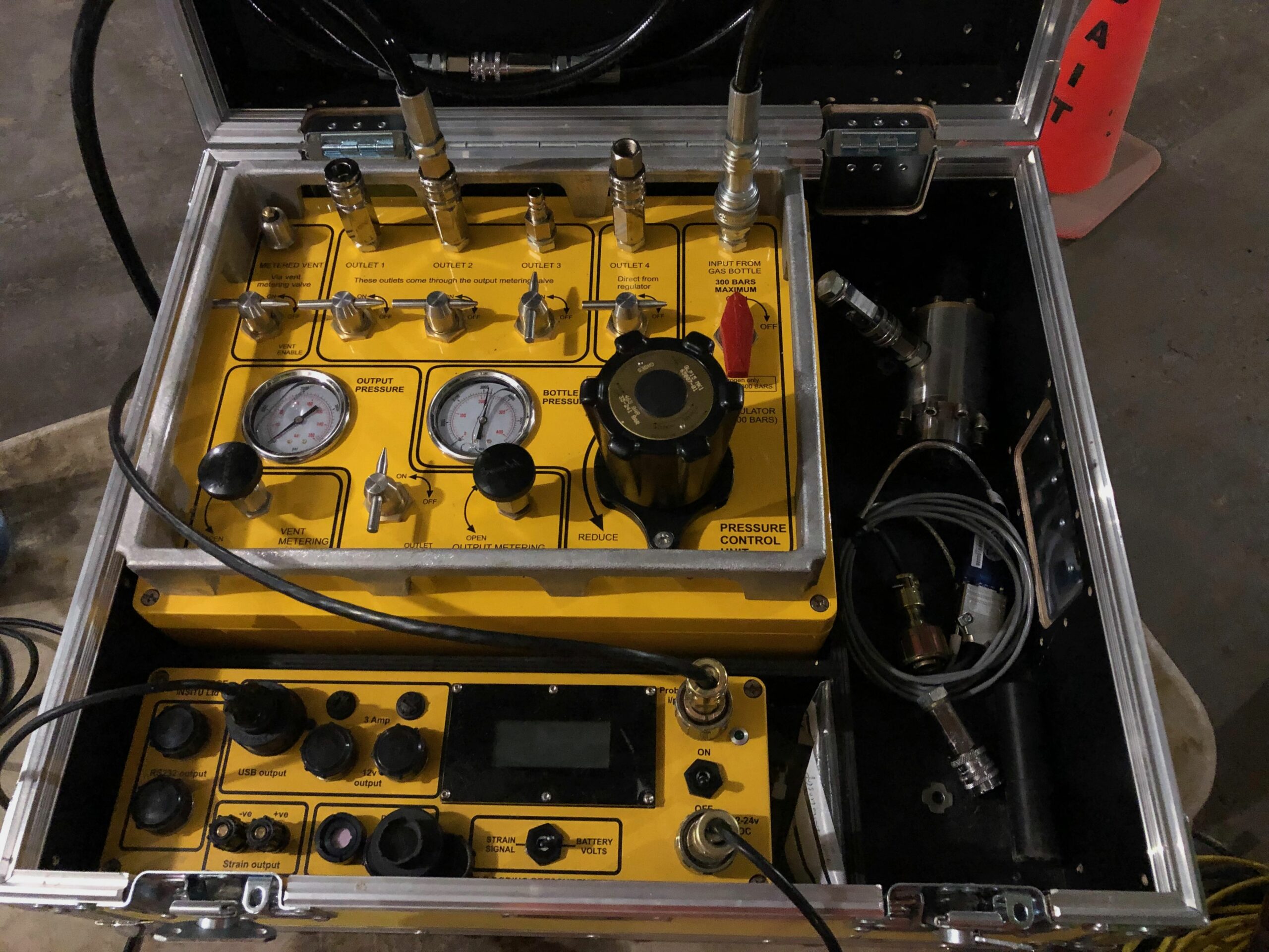
Figure 2. High pressure control panel used at surface by the engineer/operator to dictate a radial displacement pressuremeter test. Photo by Cambridge Insitu Ltd, 2022
During testing, the borehole wall is loaded as a cylindrical cavity. The change in pressure and resulting movement of the cavity are recorded. This demonstrates a cavity expansion with an increase in cavity strain, allowing for a closed form analytical solution. It is possible to avoid empiricism, depending on the specific pressuremeter used. The way the instrument’s pressure is controlled by the operator entirely dictates the type and quality of the test, as does the insertion technique.
Some of the pressuremeters outlined in this article have the capacity to measure direct pressure and direct displacement, which can be converted into stress and strain. From here, the pressuremeter data can be analysed to produce key engineering parameters for geotechnical design. This procedure requires careful categorisation of the data. Transparent data processing and appropriate analysis is vital to ensure accurate determination of geotechnical parameters.
Some of the parameters that can be derived from pressuremeter data include the following:
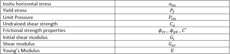
The Pressuremeters
Several types of pressuremeter exist, suiting different applications and ground conditions. However, most pressuremeters have a cylindrical flexible membrane which expands when pressure is applied (like inflating a balloon). During a live test compressed air or oil is applied down an umbilical. This then causes the flexible membrane to expand, causing the borehole wall to deform.
In addition to the above description of a typical pressuremeter, is the Flat Dilatometer (DMT) or Machetti Flat Blade Dilatometer, which operates in a different manor. This consists of a flat metal blade with a flush circular steel membrane on one side. The DMT is driven into ground using a Cone Penetration Testing (CPT) rig or drilling rig. The metal membrane is then pressurised with compressed gas and expansion measured at specific, given, points through the test period.
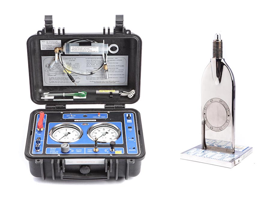
Figure 3. A Flat Dilatometer. Photo by Studio Prof. Marchetti S.r.l.
From here, these instruments can be divided into those that measure a change in volume and pressure, and those that directly measure down-hole pressure and radial displacement.
Ménard Pressuremeters
The former are Ménard pressuremeters and have a more “classical” design. They measure a change in fluid volume as opposed to radial displacement, as well as measuring fluid pressure. The sensors for measuring these variables tend to be on surface as opposed to down-hole. Some modern versions of this style of pressuremeter provide a digital output. These instruments provide a different set of data to radial displacement pressuremeters owing to the lack of directly measured displacement data. Hence the “Ménard modulus” is the primary output of the analysis.
Radial Displacement Pressuremeters
The latter are radial displacement pressuremeters, sometimes called “Cambridge pressuremeters”. These are instrumented probes; that is to say, down-hole measurements are taken directly via strain gauge transducers (sets of either 3 or 6), spaced evenly around the probe. These strain gauges measure the displacement of the membrane continuously during a test. A further transducer measures the internal total pressure of the probe during the test. Combined, the transducers provide incredibly precise and reliable data for pressure (stress) and displacement (strain). Transducer resolutions can equal 0.1KPa Pascals and 0.3 Microns. The output of these instruments appears as a live data stream on a graph viewed via software.
There are three main types of radial displacement pressuremeter. These three are all based on the same concept as outlined above, as they all have capacity to measure stress and strain during a test. The below table explains some of the individualities of each.
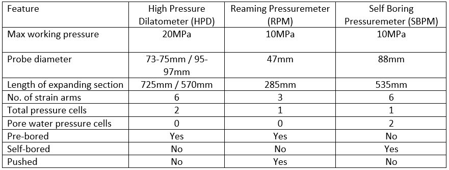

Figure 4. Rendered CAD images of some radial displacement pressuremeters. From top to bottom; 95HPD, 95HPD (Short), SBPM, RPM. Photo by Cambridge Insitu Ltd, 2022
These instruments can be operated in a variety of materials, from very low strength clay or silt and loose sand to high strength rock. They can also be operated from in a wide variety of environments, both on land and overwater. A common application is in conjunction with a rotary drilling rig, as these have the capability to work with all types of pressuremeter mentioned above. Some probes can also be deployed with a standard piezocone attached from a cone penetration testing platform.
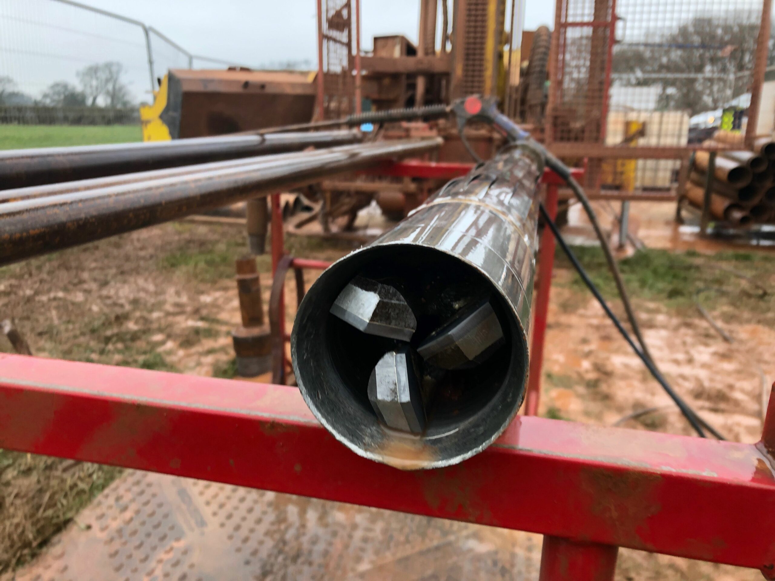
Figure 5. A self boring pressuremeter, the cutting shoe and internally positioned drag-bit are clearly visible. Photo by Cambridge Insitu Ltd, 2022
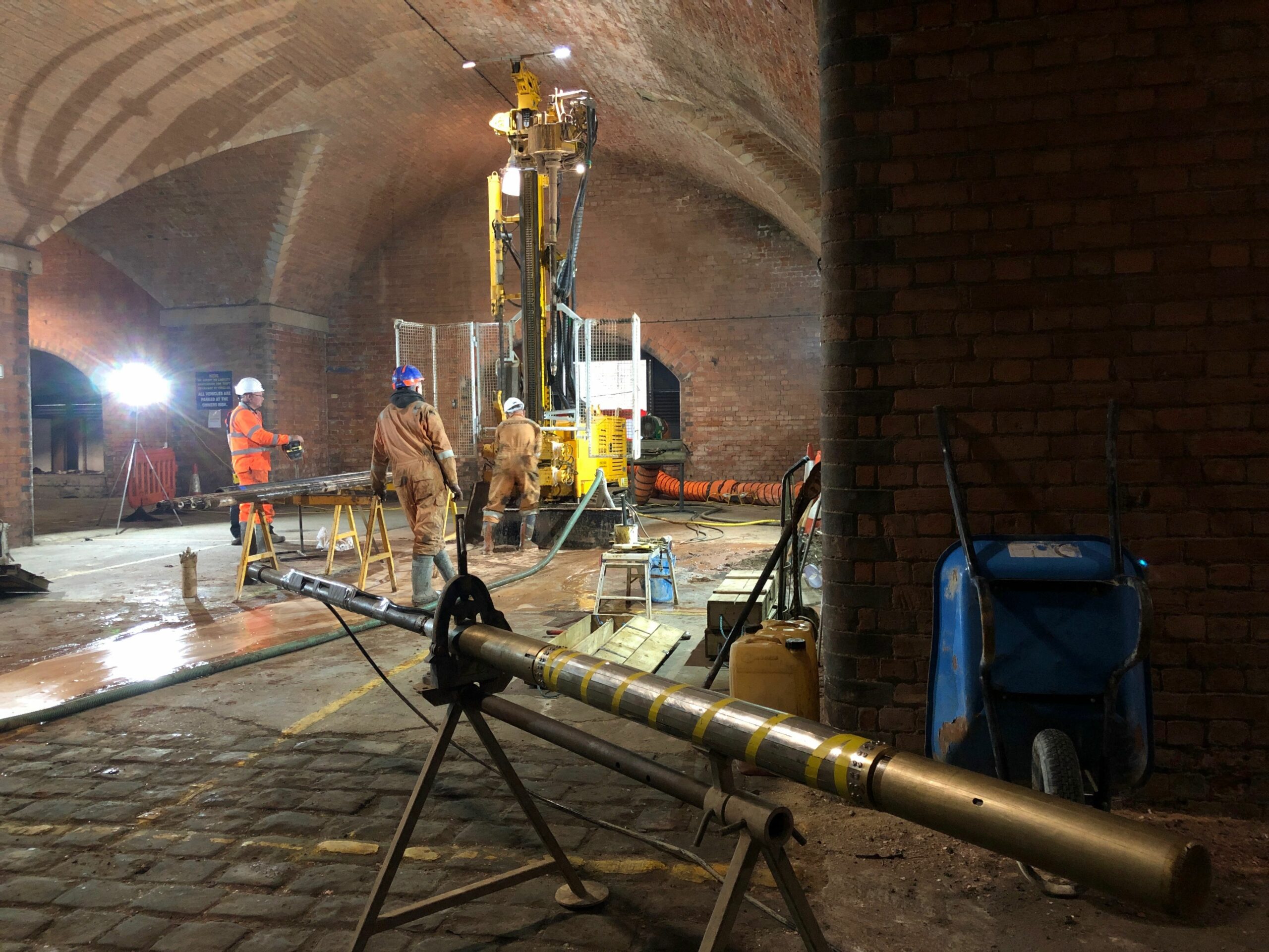
Figure 6. A high pressure dilatometer ready for deployment under a rotary drilling rig. Photo by Cambridge Insitu Ltd, 2022
Analysis Process
The process to convert the raw data these instruments produce into the relevant engineering parameters can be complex. The quality of the test will dictate the confidence in the parameters that can produced.
To achieve the maximum return from pressuremeter testing, the desired outcomes must be considered from the start. Instrument selection, insertion technique and specific or bespoke testing procedures should be considered to match with the expected geology and the desired parameters.
Once the appropriate approach to the testing has been decided, the tests must be completed in a way that provides high quality data without missing any key parts of the material response. For instance, a test that does not reach a large enough strain in a material may mean that confidence in observed strength parameters is undermined, even if the insitu stress is the primary focus of the investigation.
The actual analytical process is focussed around using directly measured techniques for each parameter. Subsequently, a curve modelling technique is utilised to provide an optimised solution to the desired parameters. This process allows both the directly measured and modelling techniques be considered, introducing data redundancy, and providing high levels of confidence.
Authors
Thomas Cragg – Cambridge Insitu Ltd – thomas@cambridge-insitu.com
John Holt (Senior Geologist) – In Situ Site Investigation Ltd – johnholt@insitusi.com