The article entitled “are traditional sampling techniques really that bad” published in April’s AGS Magazine has provoked much discussion and debate amongst AGS members and within the industry. The Geotechnical Working Group has been exploring how the UK geotechnical industry can respond to the demands of our clients and updates to Eurocodes and other standards to deliver investigations that enable project design of appropriate quality. This article is intended to put the views expressed in the April article into context and propose how the full range of investigation options can be better used to deliver projects that meet the challenges of delivering our client’s needs now and in the future.
Whilst design, analysis, and construction techniques have evolved and benefited from market innovation and new techniques, many of the ‘traditional’ investigation methods have not changed in the past 100 years. For example, the process of driving piles now benefits from instrumentation and automatic logging of construction conditions and the driving process. This enables the piling specialist to feed this data back to designers and contractors to allow rapid verification of pile capacity, design modification, and communication to the supply chain. In contrast, the humble SPT, which forms the basis of much of the foundation design delivered in the UK, has not benefited from any significant improvement in the way information is gathered about the in-situ state of the ground.
It is true to say that there is often a conflict between cost and perceived benefit and for the uninitiated the decisions which determine the methodology used to investigate the ground conditions and the determination of design parameters is often, if not invariably, determined by cost rather than technical requirement or necessity.
This conflict has in the past been minimised by using large factors of safety. Historically, geotechnical engineers have used this factor of safety and combined it with engineering judgement to allow for variations and uncertainties within the ground, however, it is now far too often just used as a margin for error or in many cases poor quality control. This latter approach provided the comfort of knowing that even if the results were not that accurate, it really did not not matter, because failure was very unlikely. It is important to note that whilst there have been few foundation failures as a result of bearing capacity, the same is not true of structural distress due to differential settlement. This fact reflects more about our inability to accurately determine soil stiffness rather than determine the undrained shear strength. The advent of Eurocode and more precisely the use of limit state design and partial factors has removed the comfort which for many years has disguised poor practice or inappropriate investigation methods.
It is true that many clients and design teams have not fully embraced Eurocodes, however, there is a misconception that there is a choice to design either using the old methods or Eurocodes. This is a dangerous path to tread, because the old standards are no longer supported by BSi and effectively are now obsolete. The UK has always been fully committed to using Eurocodes or perhaps more correctly the new British Standards and Codes of Practice which are fully complimentary with Eurocode. The decision to follow this route was made many years ago and was embraced by our governing bodies and Institutes and indeed the UK, through AGS and other bodies, has and still does play a significant role in their content.
It is interesting to read the views given on the use of the SPT and the premise that these tests are often adopted rather than rotary coring. This is a misconception which has no technical foundation, perhaps we forget that the SPT was originally developed as a sampling tool and not an in-situ test. It was configured as a split spoon with an open shoe and in this form is a thick walled sampler in current terminology. The number of blows to drive the sample was originally something which was added to provide a bit more information on ease of penetration. More importantly under Eurocode 7 the SPT is classified as a secondary investigation method which should be used to complement soil strength measurements derived from laboratory testing of Class 1 soil samples. Unfortunately, in many cases, the SPT is still presented as the primary source of data to interpret in-situ soil strength.
The SPT, as we know it today, was first described by Karl Terzaghi and Ralph Peck in their book published in 1947. At that time, the equipment had been in use for more than 30 years as a sampling tool, albeit rather crude. The sample is invariably highly disturbed and of limited value. The original equipment was modelled around similar equipment used in the USA and attributed to Colonel Charles R Gow in 1902. The original sampler, which was 1 inch in diameter, was driven at the bottom of the borehole using a 110lb hammer. Around 1927, part of the Raymond Piling Group, the Gow Company began using a split spoon sampler of 2 inch diameter. Around the same time, a similar system was being used by Sprague and Henwood. In both systems the weight was winched by hand and released at a fixed height. The split spoon sampling tool which comprised a thick walled tube with a cutting shoe on one end was driven into the bottom of a borehole with blows from the hammer. The use of powered winches was not reported until 1937. The equipment was not standardised and it is recorded that the drop weight ranged from 110lb to 140lb whilst the height the weight was dropped was related to that which men could comfortably lift, usually 30 inches. It was not until Terzaghi and Peck (1947), when describing the sampling system, suggested that the number of blows be recorded as those required to drive the sampler 1 foot following seating the sampler 6 inches beyond the base of the borehole. Terzaghi suggested that by recording the number of blows valuable information might be obtained at little cost and that the information may be of some use in soils where little other information could be obtained such as granular (coarse) soils. Up to this point there were no other tests which might indicate the potential competence of granular (coarse) soils. Terzaghi proposed to use a 60 degree cone rather than an open shoe and then count the number of blows taken to drive the cone a given distance. This has been standardised into the test form we use today. It should also be noted that the test has only recently been standardised around the world and in some countries the test still does not follow a unified method.
The open shoe often blocked off on gravel and would then produce erratic results. For much of the next 70 years or more, the SPT was used to give something to assist engineers to determine the nature of granular (coarse) soils. Various authors have attempted to derive more useful parameters from these basic results. Many of these relationships are based on sound research but most are only relevant to the original site the work was carried out on and are not readily transposable to other sites.
It was in the 1980s that the now common use of taking an SPT in fine soils began to gain acceptance, again, several authors attempted to develop relationships which are at best tentative.
The SPT test is at best crude and often a blunt tool used to provide information of debatable value. In practice the cone is driven dynamically over a distance which far exceeds any strains the ground will be subjected to by loadings from foundations. The SPT is certainly not a replacement for laboratory testing of good quality soil samples no matter how cheap.
It is interesting to see the energy ratio (calibration) test results for the five hammers used by Soils Consultants. It is true that the introduction of an annual inspection and test has undoubtedly improved the maintenance of the equipment. However, the variation in the obtained energy ratio values reflects the inherent uncertainty of the test and probably also points towards the variation in the different equipment used to measure energy ratio by different test houses. It also highlights how the test can be affected by numerous other factors which were described by Clayton, 1982 as ‘parasitic effects’. The suggested energy ratio calculation can create some inconsistencies between individual calibration tests and test houses as it only requires the energy ratio to be reported as the mean value of at least five measurements (blows). Extensive testing and analysis by the Equipe Group has proven that by recording at least ten blows can provide a more representative mean value and can also eliminate the effect of spurious results. Some test units simply take the average of the five blows no matter how wide the range of individual determinations might be. It is clear the test should be more rigorous, limiting the range not to exceed values of say no more than 10% of the mean. Note that BS EN ISO 22476-2 suggests that measured energy for dynamic probing equipment should not deviate more than 3% of the theoretical energy. Hammers testing outside this range should be considered as defective as any results obtained from this equipment are unlikely to be reliable, consistent or representative. The uptake of such testing has improved in recent times but it is interesting to note that BS EN ISO 22476 – 3 was published in 2005. However, it was not until 2008 when Equipe introduced an independent testing service were we in the UK, able to even measure the energy ratio.
The previous article, published in the May edition of the AGS Magazine, has presented data showing a wide scatter of test results from various methods (Graph 1). This graph provides evidence that the London Clay is far from homogeneous, with values of Cu and SPT varying considerably through the formation. This is not surprising when considering the work of King et al, 1981 which identified some four divisions and 12 subdivisions in the formation. Indeed, a visit to the classic exposure at Whitecliff Bay, IOW will demonstrate how much variability is contained within the sequence.
The data in Graph 1 reinforces the need to investigate each site as an individual location and to use the best possible methods to obtain reliable data to ensure that the parameters sourced are as representative as possible for the specific design requirement of any particular site. Indeed, the data presented demonstrates how difficult it is to try to over simplify the data and analyse amalgamated results. Designers all too frequently seek to draw straight lines which are used as design lines or even give an upper and lower bound. This design approach often ignores the natural variability of the materials. This variability is further demonstrated by Standing, 2018 who used water content to determine the boundaries between the divisions identified by King. His work clearly identifies the variability of water content in the various divisions and geotechnical practitioners are very aware that water content will directly affect the measured undrained shear strength.
Whilst not wanting to disregard all of the current investigation methods used to obtain geotechnical parameters for design purposes, it is important to bear in mind that sampling methods which use driven thick walled sampling tubes will produce disturbance of both structure and water content distribution through the sample. This is clearly demonstrated by the fact that much of the London Clay is laminated but it is very rare that these laminae are seen in driven tube samples whilst they are seen to be present in high quality rotary cores. Tube samples usually exhibit a softer outer skin which is developed by pore water suctions being developed as the tube is driven, causing water to migrate from the centre of the core to the outer edge. This moisture migration will affect the undrained shear strength when tested in the triaxial apparatus.
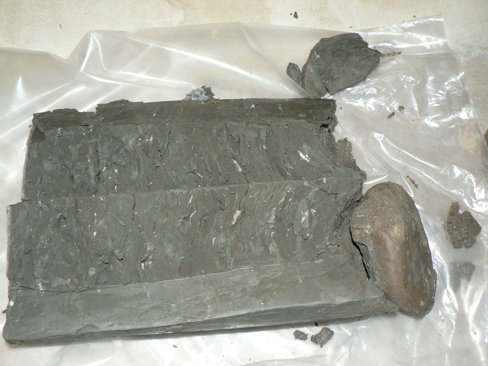
U100 sample taken in a stiff laminated clay showing acute sample disturbance (The lump at the base is wax.)
The variability of the London Clay is also clearly exhibited by CPT tests carried out within the sequence. These demonstrate the variability over short distances and reinforce the argument that the formation does not conform to straight lines. Therefore, designs which result from straight line analyses are likely to be prone to simplifying the in-situ ground conditions which could lead to errors in interpretation..
For many years the geotechnical community have chosen to ignore the obvious and often stated limitations of both the SPT test and driven samples. Of the SPT, Clayton et al stated that in granular (coarse) soils, the SPT results can only be correlated in a general way with physical properties whilst in cohesive (fine) soils the results can be regarded as generally unreliable. This was further reiterated in 1995 by Clayton and again in 2001 by Prof. Paul Mayne. Simons, 2001 cite sound research to support these opinions.
The evidence produced by many authors shows that both thick walled sample tubes and SPT testing provides very poor results and cannot be recommended for the reliable determination of design parameters. Eurocode clearly labels these samples as Class 3 or 2 and as such unsuitable for strength or deformation testing. The UK’s recommended design methods using codes which have been decades in their production and compiled by respected members of our engineering community require that good practice must be followed to ensure a safe and economic design. The essence of Eurocode is one of a complete document which serves to ensure the design method is supported by good practice and not a document where specific parts can be lifted as one feels fit, whilst other parts are ignored.
Surely it is time that we embrace the technology at our disposal to ensure ground investigation is conducted properly and to the standards we would expect in almost any other walk of life. Relying on the results of a steel rod or tube knocked into the ground does not constitute best design practice in the 21st century.
We are not advocating that the SPT is going to be consigned to the museum, however, as a start point we must surely be able to take out some of the errors which are sadly still apparent, this might include electronic measurement of the depth of penetration along with the number and energy of blows delivered to the rods.
There is still much to do if we are to move on from the SPT and driven sampling methods, however, we do need to put our faith in our ability to find solutions. It is time to invest in research to develop reliable methods to determine water content, density and stiffness. It is only by doing this, that we will be able to provide workable economic designs and alternatives to outmoded and scientifically unsuitable methods.
There is little point in appeasing the client by keeping costs as low as possible and then providing the wrong answer which can tarnish professional reputations and test the strength of your PI insurance..
References
King C. 1981. The stratigraphy of the London Basin and associated deposits. Tertiary Research Special Paper, 6 Bachuys Rotterdam.
Standing J. R. 2018. Identification and implications of the London Clay Formation divisions from an engineering perspective. Proceedings of the geologists association 2018.
Clayton C.R.I, Simons N.E. and Mathews M.C. 1982. Site Investigation. Granada
Clayton C.R.I. 1995. The Standard Penetration Test (SPT): Methods and Use. CIRIA Report 143. London: CIRIA 143.
Simons N. E. and Menzies B. K. 2001. A short course in foundation engineering. (2nd edition) Thomas Telford Publishing London.
Mayne P. W. 2001. Ground property characterisation by Insitu tests. Proc.15th ICSMGE Istanbul.
British Standards Institute. 2015. BS 5930 Code of Practice for Site Investigation.
Article provided by Peter Reading (Geotechnical Consulting) and Stephen Lawrence West (Ramboll)