Introduction
The use of the Dynamic Cone Penetrometer (DCP) also commonly known in the UK as the TRL Penetrometer or TRL Probe has been under discussion recently in the AGS Safety and Geotechnical Working Groups due to concerns raised by members regarding the significant danger of injury from damage to underground utilities, manual handling injury and the quality of the geotechnical data output.
The Dynamic Cone Penetrometer (DCP) is an instrument designed for the rapid in-situ measurement of the structural properties of existing road pavements constructed of unbound materials. The robust and simple design means that the DCP is quick and easy to use, portable, low cost and suitable for use in locations where access may be difficult. It is commonly used in the UK to determine a California Bearing Ratio (CBR) profile for pavement design.
This article discusses the history of the test, the safety concerns and geotechnical design limitations of the DCP in modern practice and provides alternative methods which must be considered by the Designer.
Historical Background
The earliest technical references to the Dynamic Cone Penetrometer (DCP) suggest that it was developed in 1959 by Professor George F. Sowers, Professor of Civil Engineering, Georgia institute of Technology, Atlanta, USA1. The original DCP used a 15 lb weight dropping over 20 ins and used a 40o cone. This DCP was originally developed for field exploration and for verifying individual footing foundations during construction. The DCP was further developed in South Africa for the evaluation of in-situ pavement strength or stiffness of newly constructed roads in the 1960s. Dr. D. J. van Vuuren designed this version of the DCP with a 30° cone2.
The Transvaal Roads Department in South Africa began using the DCP to investigate road pavement in 19733. Kleyn reported the relative results obtained using a 30° cone and a 60° cone. In 19824, Kleyn described another DCP design, which used a 60° cone tip, 8 kg (17.6 lb) hammer, and 575 mm (22.6 in) free fall. This design was then gradually adopted by countries around the globe including the USA and by Transport Research Laboratory (TRL) in the UK. In 2004, the ASTM D6951-03 Standard Test Method for Use of the Dynamic Cone Penetrometer in Shallow Pavement Applications described using a DCP with this latest design5.
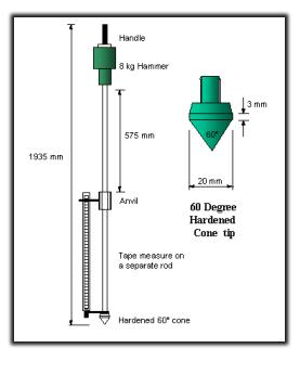 Typical DCP/TRL Probe
DCP Procedure
The 8 kg free fall hammer is manually lifted and dropped through a height of 575mm. The distance of penetration of the cone tip is then recorded and the cycle repeated. Continuous measurements can be made down to a depth of approximately 850mm or when extension rods are fitted to a maximum recommended depth of 2 metres.
DCP testing consists of using the DCP’s free-falling hammer to strike the cone, causing the cone to penetrate the base or subgrade soil, and then measuring the penetration per blow, also called the penetration rate (PR), in mm/blow. This measurement denotes the stiffness of the tested material, with a smaller PR number indicating a stiffer material. In other words, the PR is a measurement of the penetrability of the subgrade soil.
Technical Output from the DCP
The most common use of the Dynamic Cone Penetrometer (DCP) is to provide a quick and simple field test method for evaluating the in-situ stiffness of base and subgrade layers for roads and highways, and DCP testing has been used in many countries and US States for subgrade evaluation and QA/QC procedures. The greatest advantage offered by the DCP is its ability to penetrate underlying layers and accurately locate zones of weakness within the pavement system.
Correlations have been established between measurements with the DCP and conventional in-situ CBR so that results can be interpreted and compared with CBR specifications for pavement design. TRL Report TRL5875 is the most common correlation method used in the UK and is widely specified. A typical test takes only a few minutes and therefore the instrument provides a very efficient method for obtaining information which would normally require the digging of test pits.
Technical Limitations
This instrument is typically used to assess material properties down to a depth of 1000 mm below the surface. The penetration depth can be increased using drive rod extensions. However, if drive rod extensions are used, care should be taken when using correlations to estimate other parameters, since these correlations are only appropriate for specific DCP configurations. The mass and inertia of the device will change and skin friction along drive rod extensions will occur.
Correlations to CBR in homogenous, fine grained soil types are potentially the best use of the tool, or for finding boundaries of known (engineered or natural) layers where there is significant difference in resistance i.e. soft clay over dense gravel. Heterogenous soil types, e.g. Made Ground, with a recommended CBR from DCP may represent a false materials characterisation presented in a report to a civils designer not fully understanding the technique’s limitations.
Health and Safety Concerns
The nature of the test means it is manually operated from ground level without view of the materials and ground conditions being penetrated. The standard equipment comprises in basic terms a metal cone which is connected to metal rods which are driven into the ground using a metal weight and slide mechanism. Incidences of personal injury from manually driving or pushing metal spikes or road pins into buried services have been well documented and must be considered a significant risk. The equipment is not insulated and the procedure requires the operative to hold the equipment6,7 and includes the potential to force-drive through obstructions which might include unobserved buried services.
Although not a DCP test but effectively a similar process, AGS in 2017 (SP Energy Networks) reported an incident where an operative drove a steel road pin into a HV electrical cable and more recently a Safety Alert was released by Geoffrey Osborne in 2019 relating to a similar incident. Driving of road pins on Network Rail requires a permit as it is deemed a significant risk and many contractors have banned the use of road pins or the driving of other metal rods (i.e. earth spikes) into the ground.
With regard to manual handling, the equipment is bulky and unstable unless held firmly at what may be head height for some operators including the 8 kg hammer at the top. Generally, it requires two persons to perform the operation, but is often carried out by single operators to minimise cost. Although some DCP systems have mechanical jacks to extract the rods the typical use in the UK is by back hammering or manual pulling if there is resistance during extraction of the rods and cone. These practices could lead to not only damage of the equipment but the risk of musculoskeletal injuries must be considered.
The device was designed before modern standards in health protection, or the practicality of manual handling in a more regulated industry was considered. It is the role of the Designer in CDM to reduce or preferably eliminate risks. Designers specifying a DCP as part of a compliant ground investigation to obtain data for pavement design are simply failing in their CDM duty where this hazard is identified because a CBR value can be obtained in a safer way which can reduce or even eliminate the risk.
Alternative methods for CBR
The common practice to determine CBR values before DCPs were through collecting a bulk sample from hand excavated pits and carrying out laboratory testing. It is acknowledged that excavating a trial pit to obtain a sample is not without risk, but that is a recognised industry methodology and would be expected to have mitigation to avoid underground services strikes.
In situ CBR values can be obtained from surface or the base of a hand excavated trial pit using In-situ CBR equipment or Plate Load Test (PLT) equipment in accordance with BS 1377 procedures. The limitation of these tests is that they only provide a single value and not a profile and results can be detrimentally affected by coarse materials in mixed soils or near surface desiccation in fine soils.
If a CBR by depth profile is essential for design then the use of equipment such as the Lightweight Deflectometer (LWD) could be considered. The LWD is a device that estimates the in-situ modulus of a material using the impulse load produced by the impact of a falling weight. LWDs are particularly useful for estimating the moduli of asphalt, aggregate base, granular subbase and subgrade pavement layers. LWDs consist of a mass (often 10 kg), an accelerometer or geophone, and a data collection unit and are designed to be light enough to be moved and operated by one person.
Conclusions
The use of DCP to provide QA/QC data for newly constructed highways and earthworks where the location of buried services is known is considered to be a useful, quick, low cost and relatively low risk method. However, when DCPs are specified along routes for new highways or more generally to determine CBR values for pavement design the risk becomes significantly greater from injury through damage to buried services and the method has technical and quality concerns.
The method has been extended for purposes beyond its original design which often do not take into account the modern environment. The construction CBR value provided through laboratory testing which also provides soil type and compacted density, or through an in-situ surface test such as In-situ CBR/PLT is recommended as being faithful to the original correlation with Californian rock gravel performance under relevant loading conditions.
The use of LWD equipment could reduce both the risk of injury from damage to buried services and manual handling even further and this method will provide a CBR depth profile which is now the most common reason in ground investigations for specifying a DCP.
The justification for the Designer to specify DCP must be carefully considered and not driven by lowest cost and a robust risk assessment must be carried out. Ground investigations, especially those on brownfield sites, using the DCP may not be considering the technical limitations of the test and may not fully take into account the safety risks. Therefore, Designers under CDM may be failing in their duty to eliminate or reduce risk and through specifying DCPs are putting persons at harm.
The AGS is currently considering the safe use of DCPs and alternative methods in order to reduce or eliminate the safety risks to members. It would welcome opinions and thoughts from its members and also technical data which could support the promotion of alternative methods.
References
1 George F. Sowers and Charles S. Hedges: 1966 : Dynamic Cone for Shallow In-Situ Penetration Testing – Vane Shear and Cone Penetration Resistance Testing of In-Situ Soils, ASTM STP 399, Am. Soc. Testing Mats., p. 29.
2 van Vuuren, D. J. : 1969 : Rapid Determination of CBR with the Portable Dynamic Cone Penetrometer, The Rhodesian Engineer.
3 Kleyn, E. G. : 1975 : The Use of the Dynamic Cone Penetrometer (DCP). Transvaal Roads Department, South Africa.
4 Kleyn, E. G., Maree, J. H., and Savage, P. F. : 1982 : The Application of a Portable Pavement Dynamic Cone Penetrometer to Determine in situ Bearing Properties of Road Pavement Layers and Subgrades in South Africa. The European Symposium on Penetration Testing, Amsterdam, Netherlands.
5 ASTM D6951 / D6951M – 18 : 2018 : Standard Test Method for Use of the Dynamic Cone Penetrometer in Shallow Pavement Applications.
6 Zohrabi, M and Scott, P.L : 2003 : TRL Report TRL587, The correlation between the CBR value and penetrability of pavement construction material. Transport Research Laboratory
7 Done, S.; Samuel, P. : 2004 :User manual UK DCP 2.2. Measurement of road pavement strength by Dynamic Cone Penetrometer.
8 Jones C R and J Rolt (1991). Operating instructions for the TRL dynamic cone penetrometer (2nd edition). Information Note. Crowthorne: Transport Research Laboratory.
9 BS 1377 : 1990 : Methods of test for soils for civil engineering purposes. British Standards Institute
Article contributed by James Harrison, previously Delta Simons and Julian Lovell, Equipe Group